The biggest mistake in ATEX compliance for facilities like flour mills or wood shops is treating fine dust as less dangerous than gas; in reality, it’s often a more insidious and widespread explosion risk.
- Effective compliance isn’t about memorising legal text, but about understanding and breaking the “Explosion Pentagon”: fuel, oxygen, ignition, dispersion, and confinement.
- You can often significantly reduce compliance costs by using engineering controls like ventilation to downgrade hazardous zones, rather than buying expensive ATEX-rated equipment.
Recommendation: Start by mapping your own facility’s “risk hotspots” to visualise where dust clouds can form, then focus on controlling ignition sources in those specific areas.
As a plant manager in a flour mill or woodworking shop, you’ve seen it a thousand times: a fine layer of dust coating every surface. It seems like a simple housekeeping issue, but is it something more? You’ve heard about ATEX and DSEAR (The Dangerous Substances and Explosive Atmospheres Regulations 2002), but the guidance often feels abstract, focusing on flammable gases and chemical vapours that don’t seem relevant to your daily operations. The regulations appear complex, the zones (0, 1, 2) confusing, and the only clear advice is often to “hire an expensive consultant.”
This approach leaves you feeling powerless and uncertain about the very real risks your team faces. The common advice overlooks a critical fact: for many industries, the primary explosive risk comes not from a leaking gas pipe, but from the seemingly innocuous dust generated by your core processes. Trying to apply gas-centric logic to dust hazards is a recipe for confusion and, worse, a false sense of security.
But what if the key to compliance wasn’t buried in legal jargon, but in basic physics? The truth is, ATEX compliance is about understanding the simple chain reaction of an explosion and systematically breaking that chain. It’s about seeing your plant not through the eyes of a lawyer, but through the eyes of a physicist, identifying where fuel (dust), oxygen, and ignition can meet. This guide will shift your perspective. We won’t just define the zones; we will show you how they relate to the tangible reality of your workspace. We will empower you to see the risks, understand the logic behind the rules, and identify practical, often low-cost, measures to ensure your facility is truly safe.
This article will walk you through a practical, step-by-step approach to DSEAR and ATEX compliance for dust environments. We will explore how to identify and classify your zones, choose the right equipment, and implement engineering controls that not only enhance safety but can also save you significant costs.
Table of Contents: A Practical Guide to ATEX & DSEAR for Dust Hazards
- Why flour dust is just as dangerous as natural gas in confined spaces?
- How to map your DSEAR zones without hiring an expensive consultant?
- Pneumatic vs Electrical tools: which is the safer choice for Zone 1 maintenance?
- The anti-static flooring mistake that could trigger an explosion
- How to use ventilation to downgrade a Zone 1 area to Zone 2?
- Why your standard PLCs are failing at 40°C despite rated specs?
- Why mild steel welding fumes are now reclassified as a definitive carcinogen?
- Operating in Extremes: Protecting Sensitive Electronics in High-Heat UK Foundries
Why flour dust is just as dangerous as natural gas in confined spaces?
The perception that gas is the “real” explosion risk while dust is a “messy” nuisance is a dangerous misconception. To understand the danger, we must look beyond the simple fire triangle (fuel, oxygen, heat) and consider the Explosion Pentagon. For a dust explosion to occur, you need five elements: fuel (combustible dust), oxygen (air), an ignition source, and two additional factors critical for dust: dispersion (a dust cloud) and confinement (an enclosed space like a silo, room, or ductwork). A pile of flour on the floor won’t explode, but when that same flour is kicked up into a cloud in a confined room, it becomes as volatile as natural gas.
Each particle of dust has an enormous surface area relative to its size. When dispersed in a cloud, this surface area allows it to combust almost instantaneously, creating a powerful pressure wave. A small, primary explosion can dislodge more accumulated dust from rafters and equipment, leading to a much larger and more destructive secondary explosion. In fact, about a quarter of all dust explosions globally involve wood dust, highlighting how common this hazard is in industries like yours. The key takeaway is that combustible dust is the fuel, and poor housekeeping provides the fuel for secondary blasts.
Case Study: The 2015 Bosley Mill Explosion
The tragic explosion at the Bosley Mill wood flour mill in 2015, which resulted in four fatalities, serves as a stark reminder of this principle. An investigation by the UK’s Health and Safety Executive (HSE) found a catastrophic failure in managing this risk. The official sentencing remarks revealed that there were unacceptably high levels of dust gathering on beams, rafters, and machinery throughout the mill over a six-year period. This accumulated dust provided the fuel for a devastating secondary explosion, demonstrating that neglecting dust control is not just a compliance failure but a potentially lethal oversight.
Understanding this pentagon is the first step toward effective risk management. The rest of your ATEX/DSEAR strategy is simply about systematically removing one or more of these five elements from every part of your operation.
How to map your DSEAR zones without hiring an expensive consultant?
Once you accept that dust is a serious fuel source, the next step is to map out where the risk is highest. This is the core purpose of DSEAR zoning. It’s not a bureaucratic paper-pushing exercise; it is a practical risk map of your facility. A zone is simply an area where an explosive atmosphere (a dust cloud) is, or could be, present. Your goal is to identify these areas so you can focus your control measures where they’re needed most. While complex sites often require specialists, you can perform a solid preliminary assessment yourself using official guidance.
The UK’s HSE provides the resources you need. The primary document is the Approved Code of Practice (ACOP) L138, while the INDG370 leaflet offers a simpler guide for SMEs. The process involves identifying where dangerous substances (like wood or flour dust) are handled, and then determining the likelihood of an explosive atmosphere forming. A Zone 21 area, for example, is a place where a dust cloud is likely to occur in normal operation (like near a bagging point). A Zone 22 area is where a cloud is not likely in normal operation but could happen for short periods (like from a leak or during maintenance).
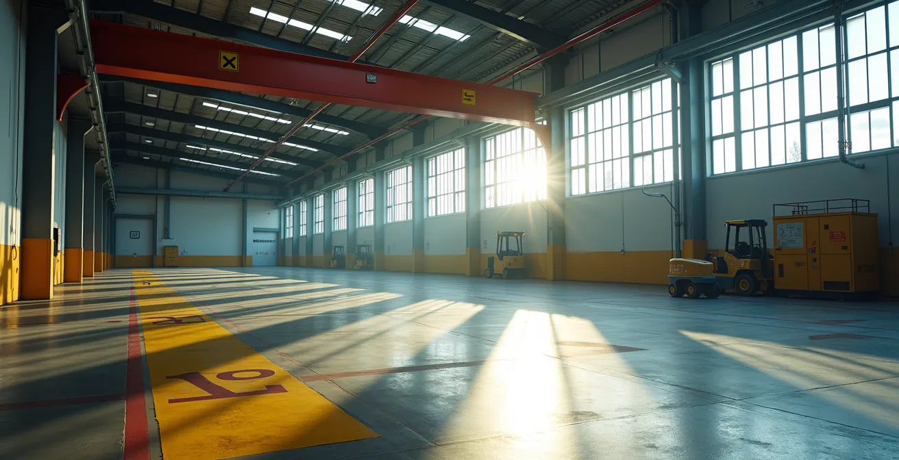
This paragraph introduces the concept of DSEAR zoning as a practical risk-mapping exercise. To better visualise this process, the image below shows a safety professional reviewing documentation against the backdrop of an industrial workspace, a critical step in translating regulatory requirements into real-world application.

As the illustration suggests, zoning is about careful observation and documentation. You need to walk your plant and ask: “Where do we have both dispersion and confinement?” Mark these areas on a plant layout diagram. This visual map is the foundation of your DSEAR risk assessment. The regulations allow for flexibility, but any decision to classify (or not classify) an area must be justified in your risk assessment. This document is your proof of due diligence. You can start this process by accessing the HSE’s official DSEAR guidance documents, which provide the framework for your assessment.
Pneumatic vs Electrical tools: which is the safer choice for Zone 1 maintenance?
After mapping where a dust cloud could form (your zones), the next step is to control the most common element of the explosion pentagon: ignition. A spark from a standard electric drill or the heat from an overheating motor can be enough to trigger a catastrophe. In ATEX-rated areas, particularly Zone 1 (gas) or Zone 21 (dust), where an explosive atmosphere is likely, your choice of equipment is not just a matter of performance, but of survival. This is where the debate between pneumatic and electrical tools becomes critical.
Electrical tools designed for ATEX zones are highly engineered. They must be housed in special flame-proof (Ex d) or increased safety (Ex e) enclosures to prevent any internal spark or heat from escaping and igniting the surrounding atmosphere. This robust protection comes at a cost, making ATEX-rated electrical equipment significantly more expensive and heavier than standard versions. Pneumatic tools, on the other hand, are often considered inherently safer for these environments. Powered by compressed air, they have no internal electrical components that can spark or generate significant heat, making them naturally suited for use in explosive atmospheres.
As the engineering team at Hearken Valve points out in their comparative guide:
A pneumatic actuator uses compressed air to provide fast (under 1s), fail-safe motion via springs, making it ideal for ATEX zones
– Hearken Valve Engineering, Pneumatic vs Electric Actuator Comparison Guide
However, the decision isn’t just about initial cost or inherent safety; it’s also about the Total Cost of Ownership (TCO), which includes energy consumption and maintenance. The following table breaks down the key differences, using data synthesized from industry guides.
| Factor | Pneumatic Tools | Electrical Tools (ATEX-rated) |
|---|---|---|
| Initial Purchase Cost | 30-50% lower purchase price | Higher upfront cost |
| Energy Efficiency | Air systems lose 80% of energy to heat during compression and friction | Electric motors convert up to 90% of electrical energy into torque |
| Annual Operating Costs | A single 1mm leak costs $500+ per year; compressed air is an expensive utility | Uses energy only during movement; cheaper over a 5-year period if used infrequently |
| Zone 0/1 Safety Compliance | Inherently safe – lack electrical components that generate heat or sparks | Requires heavy, expensive flame-proof or increased safety enclosures |
| Maintenance Requirements | Focus on seal replacement and air quality management | Minimal maintenance for quality units |
The anti-static flooring mistake that could trigger an explosion
You’ve mapped your zones and chosen spark-free tools. But what about the ignition sources you can’t see? Electrostatic discharge (ESD), the tiny spark you sometimes feel when you touch a doorknob, can be a potent ignition source for a dust cloud. In a DSEAR zone, managing static is non-negotiable. A common solution is installing anti-static or conductive flooring, but a critical mistake can render this expensive system completely useless: creating a “chain of compliance” that is incomplete.
An anti-static flooring system only works if it’s part of a continuous, grounded pathway. The floor itself is just one link in the chain. For the system to be effective, every person and every piece of mobile equipment must also be connected to it. This means mandating and testing conductive footwear for all personnel and ensuring that trolleys, carts, and mobile machinery are fitted with conductive wheels or grounding straps. If an operator walks across a conductive floor wearing standard trainers, they are building up a static charge. They become an “isolated island,” and the moment they touch a grounded piece of equipment, a spark can jump, with potentially disastrous consequences.
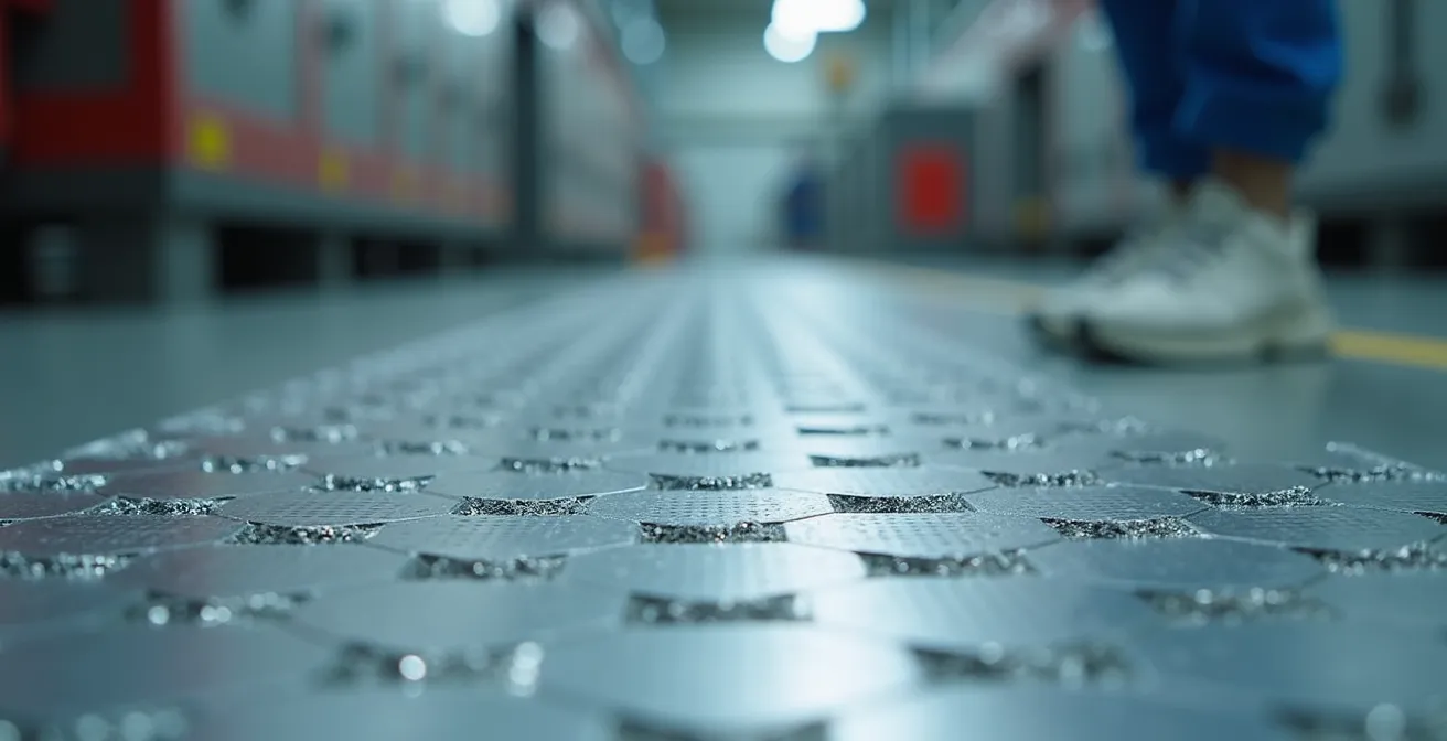
The image below provides a close-up view of the texture of anti-static flooring, highlighting the embedded conductive elements that are crucial for dissipating static charge safely. This macro perspective reminds us that safety is often built into the very materials we use.
Furthermore, the flooring itself must be correctly installed, grounded to a dedicated earth point (not mains earth), and regularly tested to ensure its conductive properties haven’t degraded due to chemical spills or physical wear. A small, isolated patch of anti-static flooring is a waste of money; it must be a complete, unbroken system. Verifying every link in this chain is a critical maintenance task.
Your Action Plan: Verifying Your Anti-Static System
- System Specification: Verify that your flooring meets the specifications outlined in BS EN 61340 for your specific zone requirements.
- Personnel & Equipment: Mandate and regularly test compatible anti-static footwear for all staff and confirm that all mobile equipment (trolleys, carts) has conductive wheels or grounding straps installed.
- Grounding Integrity: Check that the flooring is correctly bonded to a dedicated earth point, not just the building’s main electrical earth, and that there are no “isolated islands” of flooring without a proper connection.
- Resistivity Testing: Conduct regular floor resistivity tests according to British Standards (e.g., quarterly) to measure its conductive performance and log the results.
- Condition Inspection: Visually inspect the flooring for degradation factors such as deep scratches from forklift traffic, chemical spills, or contamination that could compromise its integrity.
How to use ventilation to downgrade a Zone 1 area to Zone 2?
So far, we’ve focused on controlling ignition sources within a given zone. But what if you could change the zone itself? This is a powerful and often overlooked strategy in DSEAR management called downgrading by design. Instead of spending a fortune on high-spec ATEX equipment for a Zone 21 area, you can sometimes implement engineering controls, like ventilation, to reduce the likelihood of an explosive atmosphere forming, thereby downgrading the area to a less restrictive Zone 22. This can lead to enormous cost savings on both equipment and procedures.
Ventilation attacks the “dispersion” and “confinement” elements of the Explosion Pentagon. A well-designed local exhaust ventilation (LEV) system can capture dust at its source, preventing it from ever forming a cloud. General dilution ventilation, meanwhile, can ensure that any dust that does become airborne is kept at a concentration far below its Lower Explosive Limit (LEL). According to BS EN 60079-10-1, achieving a state of “medium dilution” through effective ventilation can be a key justification for downgrading a zone.
However, relying on ventilation for safety is a serious commitment. Your system cannot be an afterthought; it must be a robust, reliable, and fail-safe engineering control. If your ventilation system is what keeps a Zone 21 from forming, it must be interlocked with the process machinery. This means installing fail-safe systems that automatically de-energise any non-Zone 2 rated equipment in the area the moment the ventilation fails. The HSE also expects audible and visual alarms to alert operators to a failure. Every decision to use ventilation for zone classification must be thoroughly documented and justified in your DSEAR risk assessment, as per the flexibility provided in Schedule 3 of the DSEAR ACOP L138.
This approach transforms ventilation from a simple comfort system into a primary safety device. It requires careful calculation of air changes per hour, continuous monitoring, and a rigorous maintenance schedule. But the payoff is significant: a safer environment and dramatically reduced capital expenditure on specialised equipment.
Why your standard PLCs are failing at 40°C despite rated specs?
In many industrial environments, from foundries to bakeries, high ambient heat is a constant challenge. This heat can become a hidden ignition source, not through a direct spark, but by causing electronic components to fail. Your Programmable Logic Controllers (PLCs) and other control electronics might be rated to operate up to 50°C or 60°C, yet you experience failures when the cabinet’s ambient temperature is only 40°C. Why? The answer lies in localized hotspots and the derating of components.
The temperature rating on a PLC is for the air immediately surrounding it. Inside a sealed control cabinet, the heat generated by power supplies, drives, and the PLCs themselves doesn’t magically disappear. Without adequate cooling, this heat creates localised hotspots where the temperature can be significantly higher than the cabinet’s average. Research shows a 15-20°C temperature differential can occur between the general cabinet air and the air right next to a heat-generating component. So, your 40°C cabinet could easily have a 60°C hotspot right on your PLC, pushing it beyond its operational limits and leading to erratic behaviour or catastrophic failure. This failure could, in turn, create an ignition source in an ATEX zone.
Effective thermal management is therefore not just about reliability; it’s a critical safety measure. The solution depends on the heat load and the external environment. A simple passive vent might be enough for low-heat applications, but in a dusty flour mill, this would invite contamination. Forced air with filtration is a better step, but for critical applications in high-heat environments, active cooling is often necessary. The following table compares common thermal management solutions.
| Solution Type | Cost Range | Effectiveness | Best Application |
|---|---|---|---|
| Passive Cooling (Vents) | Low ($50-200) | Limited (5°C reduction) | Low heat load environments |
| Forced Air with Filtration | Medium ($500-1500) | Moderate (10-15°C reduction) | Dusty environments with moderate heat |
| Vortex Cooling | Medium-High ($1000-3000) | High (20-30°C reduction) | No electrical power available |
| Active AC Units | High ($2000-5000) | Very High (30-40°C reduction) | Critical applications, high heat loads |
Why mild steel welding fumes are now reclassified as a definitive carcinogen?
While managing explosive atmospheres is a primary focus of DSEAR, your duties as a plant manager also extend to protecting your team from other dangerous substances, a responsibility governed by COSHH (Control of Substances Hazardous to Health). A significant recent change in this area is the reclassification of welding fumes. For years, only fumes from materials like stainless steel were considered highly toxic. That has changed dramatically.
In 2019, the UK’s HSE issued a safety alert that fundamentally changed the legal requirements for welding operations. Based on new scientific evidence from the International Agency for Research on Cancer (IARC), fumes from welding mild steel are no longer considered a benign nuisance; they are now classified as a human carcinogen. This means that exposure to any welding fume, regardless of the metal, must be controlled. The old excuse of “it’s just mild steel” is no longer legally or morally acceptable. According to the HSE, this reclassification has an immediate legal impact on the duties of UK employers to protect their workers.
This places a clear responsibility on you to ensure that adequate control measures are in place for all welding activities, even for short-duration maintenance tasks. The expectation is no longer simply about providing good general ventilation. Instead, you must follow a strict hierarchy of controls to manage the risk. This hierarchy prioritises eliminating the risk at its source over relying on personal protective equipment (PPE) as a last resort.
The required control measures include, in order of preference:
- Elimination/Substitution: Can the weld be designed out of the process entirely, using mechanical fasteners or bonding instead? Can a process that generates fewer fumes, like TIG welding, be used instead of MMA?
- Engineering Controls: The primary control measure should now be Local Exhaust Ventilation (LEV). On-torch extraction, which captures fumes directly at the weld point, is considered the most effective solution.
- Respiratory Protective Equipment (RPE): If engineering controls cannot sufficiently control exposure, you must provide suitable RPE. A minimum Assigned Protection Factor (APF) of 20 is typically required for general welding, rising to APF 40 for work in confined spaces.
This shift means that health surveillance programs, including respiratory health checks, are also now a requirement for any workers exposed to welding fumes.
Key Takeaways
- The “Explosion Pentagon” (Fuel, Oxygen, Ignition, Dispersion, Confinement) is a more accurate risk model for dust than the simple fire triangle.
- DSEAR zoning is a practical risk-mapping exercise you can begin yourself to identify high-risk areas before calling in consultants.
- Proactively “downgrading” a zone’s classification with engineering controls like ventilation is often more cost-effective than buying expensive ATEX-rated equipment.
Operating in Extremes: Protecting Sensitive Electronics in High-Heat UK Foundries
We’ve discussed how to manage dust and heat as separate issues, but in many real-world environments like foundries, bakeries, or chemical plants, these risks are dangerously combined. A UK foundry, for instance, faces a double threat: high ambient temperatures that stress electronics and the presence of conductive or combustible dust that can cause short circuits or explosions. Protecting sensitive control systems in these conditions requires a holistic approach that goes beyond a standard IP-rated enclosure.
A simple sealed box (e.g., IP65) might keep dust out, but it also traps the heat generated by the electronics inside, creating an oven that leads to premature failure—a principle we explored with PLCs. Conversely, a fan-cooled enclosure might manage heat but can pull in fine, conductive dust that bypasses filters and settles on circuit boards, leading to short circuits. In an ATEX-zoned area, this combination of heat and dust presents a significant ignition risk. A more robust solution is needed, one that controls both the internal and external atmosphere of the enclosure.
Case Study: The ‘Ex p’ Solution in a West Midlands Foundry
A foundry in the West Midlands faced exactly this challenge. To protect critical sensors and control panels in an area with both high heat and conductive dust, they implemented an ATEX ‘Ex p’ (purged and pressurised) system. This solution involves feeding a supply of clean, pressurised air into the enclosure. This creates positive pressure, so air is always flowing out, making it impossible for dust to enter. This technique effectively creates a non-hazardous “bubble” around the sensitive electronics, even if they are located within a Zone 21 or 22 area. The equipment selection for such systems is still dictated by the zone classification, but the ‘Ex p’ method provides a reliable way to protect standard components inside the enclosure.
This pressurised approach is one of the most effective but also most costly solutions. The 5-year Total Cost of Ownership (TCO) for an ATEX Ex p system can be higher than a passive or fan-cooled enclosure, but its near-zero failure rate in harsh environments often provides a superior return on investment when factoring in the cost of downtime and replacement parts. It’s a prime example of investing in an engineering control to solve a complex environmental challenge, ensuring both operational reliability and safety compliance.
Understanding and applying these principles moves you from a reactive to a proactive state of safety management. The next logical step is to translate this knowledge into a formal, documented risk assessment for your own facility. Start by walking the plant floor with the Explosion Pentagon in mind and begin mapping your zones.