
The key to extending component life is not simply choosing a “better” alloy from a spec sheet, but identifying and neutralizing the specific metallurgical failure mechanism that will inevitably attack it.
- Standard stainless steel fails in chloride environments due to Stress Corrosion Cracking (SCC), a mechanism activated by temperature and stress.
- High-strength parts can fail catastrophically not from overload, but from hydrogen embrittlement introduced during common plating processes.
Recommendation: Shift your maintenance strategy from reactive replacement to a proactive, diagnostic approach focused on the root cause of material failure.
As a maintenance director, you’ve seen it happen. A critical component, specified to handle harsh conditions, fails prematurely. The downtime is costly, the replacement urgent. The common response is to seek a “stronger” material or a “thicker” coating, escalating a costly arms race against corrosion and wear. You follow the spec sheets, opting for 316L stainless steel in chloride-rich areas or specifying zinc plating for high-tensile bolts, yet the failures persist, sometimes with even less warning.
This cycle of failure stems from a fundamental misunderstanding. Component longevity is rarely about brute strength or a material’s brand name. The true battle is fought at a microscopic level, against specific and often counter-intuitive failure mechanisms. The real key to reliability isn’t just knowing *what* material to use, but understanding *why* a given material will fail in your precise operating environment. Is it pitting from chlorides, embrittlement from hydrogen, or microstructural changes from welding heat?
This article moves beyond the generic advice. We will operate as metallurgists, dissecting the hidden causes of failure that spec sheets don’t mention. We will explore why “good” materials go bad, how to correctly specify treatments to prevent wear, and how to make cost-justified decisions for the most extreme applications. By understanding the specific mechanism of attack, you can move from a reactive maintenance loop to a predictive strategy that engineers durability into your systems from the start.
This guide provides a structured look into the critical metallurgical decisions that prevent premature component failure. Each section addresses a common but misunderstood challenge, offering the diagnostic insight needed to extend service life and enhance operational reliability.
Contents: A Metallurgist’s Guide to Preventing Component Failure
- Why standard stainless steel pits and cracks in chloride environments?
- How to specify nitriding depths to stop gear wear?
- Inconel vs Hastelloy: which justifies the cost for high-temp valves?
- The plating mistake that causes high-tensile bolts to snap without warning
- When to use Vickers over Rockwell testing for thin coatings?
- Why TIG welding warps your battery trays and ruins seal integrity?
- Why cheap cutting tools actually cost £200 more per shift in scrap?
- Zero-Defect Manufacturing: How High-Precision Tools Cut Material Waste by 15%?
Why standard stainless steel pits and cracks in chloride environments?
Austenitic stainless steels like 304 and 316L are often the default choice for corrosion resistance, but they possess a critical vulnerability: Chloride Stress Corrosion Cracking (SCC). This failure mechanism is particularly insidious because it occurs in environments that are not considered highly corrosive and can lead to sudden, catastrophic failure of a component that appears visually intact. The failure is not a simple matter of rusting; it is a complex interplay between three factors: a susceptible material, tensile stress (from fabrication or operation), and a specific corrosive agent—chlorides.
The metallurgical reality is that the protective passive oxide layer on stainless steel, which normally prevents corrosion, breaks down in the presence of chloride ions. This breakdown initiates localized pitting. If the component is also under tensile stress and at a sufficient temperature, these pits become nucleation sites for fine, branched cracks that propagate through the material. Crucially, this mechanism has a known activation temperature. Indeed, research from SSINA confirms that chloride stress corrosion cracking rarely occurs below 60°C (150°F). This makes any warm, chloride-containing aqueous environment a high-risk zone.
Case Study: Petrochemical Waste Line Failure
A 316L stainless steel waste fuel line at a petrochemical facility, which had been in service for two decades, developed a leak at a weld. The investigation found that the line was steam traced to 110°C (230°F) and occasionally carried fluids containing hydrochloric acid. This combination of elevated temperature and chlorides, even at low concentrations, created the perfect conditions for Cl-SCC. A failure analysis revealed extensive, branched cracking on the internal surfaces, a classic signature of this failure mechanism, proving that even a “corrosion-resistant” material can fail when its specific environmental vulnerabilities are triggered.
Preventing this requires moving beyond a simple material specification and adopting a diagnostic approach. It involves identifying areas where the three critical factors—chlorides, stress, and heat—converge. Cold-worked zones, weld toes, and U-bends are common high-stress areas. For environments where operating temperatures consistently exceed 60°C, alternative materials such as duplex stainless steels or high-nickel alloys must be considered as they offer significantly higher resistance to SCC.
Your Action Plan: Diagnosing Chloride SCC Risk
- Identify High-Risk Zones: Map all stainless steel components operating above 60°C in potentially chloride-containing environments. Pay special attention to weld toes, bends, and cold-worked areas where residual stress is high.
- Check for Pitting: During inspections, look for initial signs of pitting, as these are the precursors to SCC. Even chloride concentrations as low as 10 ppm can be a threat.
- Analyze Stress Points: Review fabrication and assembly records to identify areas of high tensile stress. Consider stress-relief heat treatments for critical welded components where feasible.
- Confirm Failure Mode: If cracking is found, verify if it has a branched, tree-like structure. This is the definitive visual evidence of SCC, distinguishing it from simple fatigue cracking.
- Re-evaluate Material Selection: If the risk is confirmed, develop a plan to replace critical 300-series stainless components with more resistant materials like duplex grades, ferritic steels, or nickel alloys for the next maintenance cycle.
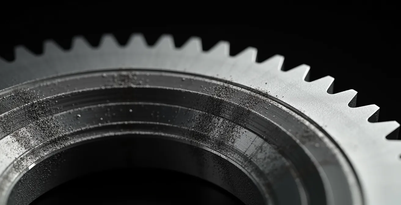
How to specify nitriding depths to stop gear wear?
For components subjected to heavy loads and sliding contact, such as gears, surface hardness is paramount to resisting wear. Nitriding is a thermochemical surface hardening process that significantly increases surface hardness and wear resistance without the distortion associated with conventional quenching. However, its effectiveness is not a given; it depends entirely on a correctly specified case depth—the thickness of the hardened layer. Specifying a case depth that is too shallow for the applied load will result in subsurface shear failure, where the hard case collapses into the softer core material.
The required nitriding depth is directly proportional to the stresses experienced by the gear tooth, which in turn relates to its size and the load it transmits. A common rule of thumb is that the effective case depth should be approximately one-tenth of the gear tooth’s base thickness. For larger gears, this requirement becomes substantial; according to Gear Solutions Magazine, gears with a tooth modulus of 15-20 mm require a case depth of 0.7 to 1 mm to adequately support the contact stresses and prevent premature failure. An insufficient depth on such a gear would be a critical design flaw.
Beyond depth, the microstructure of the nitrided layer itself must be tailored to the application. The outermost layer, known as the “white layer” or compound layer, is extremely hard but can be brittle. Its composition (a mix of ε and γ’ iron nitride phases) and thickness must be controlled. For high-precision gears, this layer is often removed entirely, whereas for applications focused purely on wear resistance, a thicker compound layer might be acceptable.
This table outlines how nitriding specifications must be adapted based on the gear’s function, demonstrating that a one-size-fits-all approach is a recipe for failure. The key is to match the metallurgical properties of the surface to the specific mechanical demands of the application.
| Application Type | White Layer Requirement | γ’/ε Phase Ratio | Surface Hardness |
|---|---|---|---|
| Power transmission gears | ≤25μm thickness | >8 (γ’ dominant) | 650-900HV |
| Wear-resistant motion gears | ε phase acceptable | Not critical | ≥500HV |
| High-precision gears | Minimal/ground off | γ’ phase only | 450-900HV |
Inconel vs Hastelloy: which justifies the cost for high-temp valves?
When operating conditions involve extreme temperatures and aggressive chemicals, stainless steels are no longer viable. The conversation then shifts to nickel-based superalloys, primarily Inconel and Hastelloy. A common mistake is to view them as interchangeable “upgrades.” In reality, they are highly specialized tools designed to combat different failure mechanisms. Choosing the wrong one is a multi-thousand-dollar mistake, as the justification for their high cost lies in their ability to resist a specific corrosive environment.
The fundamental difference lies in their alloying elements and the type of corrosion they are designed to fight. Inconel, rich in chromium, excels in oxidizing environments. It forms a stable, adherent chromium-oxide passive layer that protects it from media like sulfuric acid, nitric acid, and high-temperature oxidation. Hastelloy, with its high molybdenum and often tungsten content, is the champion in reducing environments. It is specifically engineered to withstand aggressive, non-oxidizing acids like hydrochloric acid and sour gas (H2S), where a chromium-oxide layer cannot form or is ineffective.
Therefore, the question is not “which is better?” but “what is the dominant corrosive species in my process stream?” Using Inconel in a hot hydrochloric acid stream would be a catastrophic misapplication, just as using Hastelloy where high-temperature oxidation is the primary threat would be an inefficient use of resources. This decision matrix highlights the critical factors that influence the Total Cost of Ownership (TCO) beyond the initial purchase price.
The decision to invest in a superalloy should be driven by a clear break-even analysis, not just a desire for the “best” material. If a standard stainless steel valve fails frequently due to a specific corrosive agent, the high upfront cost of a nickel alloy can be quickly justified by eliminating production downtime and replacement labor costs.
| Factor | Inconel | Hastelloy | Impact on TCO |
|---|---|---|---|
| Temperature Resistance | Up to 1000°C | Up to 1100°C | Operating range flexibility |
| Corrosion Environment | Superior in oxidizing (sulfuric, nitric) | Superior in reducing (hydrochloric acid) | Media compatibility critical |
| Weldability | Good | Moderate | In-situ repair costs |
| Lead Time | 8-12 weeks | 12-16 weeks | Inventory costs |
| Galling Resistance | Poor (requires Stellite overlay) | Poor (requires hard-facing) | Additional processing costs |
Your Action Plan: Lifecycle Break-Even Analysis Framework
- Quantify Failure Rate: Calculate the average number of failures per year for your current stainless steel valves in the target application.
- Calculate Cost of Failure: Determine the total cost of a single failure event, including lost production, labor for replacement, and the cost of the new part. This gives you the annual failure cost.
- Determine Upfront Cost Differential: Get quotes for the current stainless steel valve and the proposed nickel alloy (Inconel or Hastelloy) valve. Calculate the difference.
- Apply the Break-Even Formula: Divide the upfront cost differential by the annual failure cost of the stainless steel valve. The result is the number of years it will take for the superalloy valve to pay for itself.
- Make the Decision: If the calculated break-even point is significantly less than the expected service life of the new valve, the investment in the nickel alloy is financially justified.
The plating mistake that causes high-tensile bolts to snap without warning
One of the most dangerous failure modes in metallurgy is hydrogen embrittlement. It causes high-strength steel components, particularly fasteners like bolts and screws, to fracture suddenly under loads far below their rated tensile strength. The failure is brittle, with no plastic deformation to give warning. The cause is often a routine manufacturing step intended to protect the part: electroplating.
This is a classic “specification trap.” A designer specifies a common corrosion-resistant coating like zinc or cadmium plating for a high-strength bolt, unaware that the process itself introduces the agent of failure. During the acid cleaning (pickling) and electroplating processes, atomic hydrogen is generated at the steel’s surface. Some of this hydrogen diffuses into the metal’s crystal lattice. In lower-strength steels, this hydrogen can diffuse back out and is not a major concern. However, in high-strength steels, the hydrogen becomes trapped at internal defects, grain boundaries, and inclusions. When the bolt is put under tensile stress, these trapped hydrogen atoms reduce the energy required for cracks to form and propagate, leading to sudden, brittle failure.
There is a well-defined threshold for this risk. In fact, metallurgical research confirms that high-strength steels with tensile strength greater than 145 ksi (1000 MPa) or a hardness above ~32 HRC are highly susceptible. For any fastener exceeding this strength, specifying standard electroplating without a mitigation procedure is negligent. The mitigation is a post-plating baking process designed to drive the trapped hydrogen out of the steel before it can cause damage. The time and temperature of this bake are critical and depend directly on the steel’s strength.
The following table, based on industry standards, shows how baking parameters must be increased for stronger, more susceptible steels. The most critical parameter is the time between plating and baking; any delay allows the hydrogen to migrate to internal trap sites, rendering the subsequent bake ineffective.
| Tensile Strength | Hardness (HRC) | Temperature Range | Baking Duration | Time to Bake After Plating |
|---|---|---|---|---|
| 1000-1200 MPa | 31-38 | 190-200°C | 8-12 hours | Within 1 hour |
| 1200-1400 MPa | 39-43 | 200-210°C | 12-16 hours | Within 1 hour |
| >1400 MPa | >43 | 210-220°C | 16-24 hours | Within 1 hour |
For the most critical high-strength applications, the safest approach is to avoid processes that introduce hydrogen altogether. Alternative coating methods that do not involve acid pickling or aqueous electrodeposition, such as mechanical plating or dip-spin coatings, eliminate the risk of hydrogen embrittlement from the outset.
When to use Vickers over Rockwell testing for thin coatings?
Verifying the hardness of a protective coating is a critical quality control step. A coating that is too soft will not provide the required wear resistance. However, obtaining a meaningful hardness value on a thin layer is not as simple as putting it in a standard hardness tester. Using the wrong method, such as a conventional Rockwell test on a thin coating, can produce a completely misleading result and a false sense of security.
The problem is one of scale. A hardness test works by pressing a standardized indenter into a material with a specific force and measuring the size or depth of the resulting indentation. The test is only valid if the indentation is contained entirely within the material being measured. A Rockwell test uses a relatively high load, creating a deep indentation. If used on a thin coating, the indenter will punch through the coating and be influenced by the hardness of the underlying substrate material. The resulting reading will be a meaningless composite of the coating and substrate, not the true hardness of the coating itself.
The solution is to use a test method designed for micro-scale measurements: the Vickers microhardness test. The Vickers test uses a diamond pyramid indenter and much lower loads (often just a few grams). This creates a very small, shallow indentation that can be contained within the thin coating layer. The industry standard for ensuring a valid coating hardness measurement is the “10% rule”: the depth of the indentation must not exceed 10% of the coating’s total thickness. This prevents any influence from the substrate.
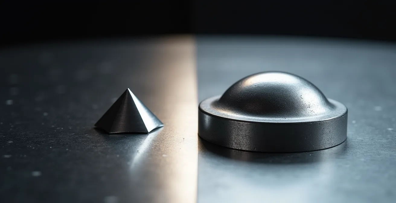
As the illustration shows, the Vickers indenter can make a valid measurement within the coating layer, while the Rockwell indenter punches through, compromising the result. For extremely thin coatings (less than 10 micrometers), even microhardness testing may be insufficient, and more advanced techniques like nanoindentation are required to accurately profile the material’s properties.
Your Action Plan: Implementing the 10% Rule for Hardness Testing
- Measure Coating Thickness: Before any hardness testing, the first step is to accurately determine the coating thickness, typically via cross-sectional microscopy on a sample part.
- Calculate Max Indentation Depth: Apply the 10% rule. For a 50 μm thick coating, the maximum allowable indentation depth is 5 μm.
- Select Test Method Based on Thickness: For coatings under 100 μm, the default choice should be Vickers microhardness, starting with a low load (e.g., 10-50 grams) to ensure the indentation is shallow enough.
- Scale Load Appropriately: For thicker coatings (100-500 μm), a Vickers test with a higher load (100-300g) may be used. Rockwell superficial scales might be acceptable for coatings over 500 μm, but verification is still required.
- Consider Nanoindentation for Ultra-Thin Films: If your application uses PVD or other coatings under 10 μm, standard microhardness is not suitable. Specify nanoindentation to get an accurate hardness profile.
Why TIG welding warps your battery trays and ruins seal integrity?
Gas Tungsten Arc Welding (TIG) is prized for its clean, high-quality welds, making it a common choice for fabricating sensitive components like battery trays for electric vehicles. However, its high, concentrated heat input creates a significant problem: a large Heat-Affected Zone (HAZ). This is the area of base material next to the weld that has not been melted but whose microstructure and properties have been altered by the heat. In thin-gauge materials like those used for battery trays, this leads to two critical failure modes: distortion and reduced corrosion resistance.
Distortion is the most visible problem. The intense, localized heat of the TIG arc causes the metal to expand rapidly, followed by contraction as it cools. This cycle of expansion and contraction in a localized area of a thin sheet creates buckling and warping. For a battery tray, this distortion is fatal to its function. It prevents the tray from seating correctly and, most importantly, compromises the integrity of the seals designed to protect the battery cells from moisture and contaminants. A warped sealing surface cannot maintain the required compression, leading to inevitable leaks.
The second, more hidden problem is metallurgical. In stainless steel trays, the heat from TIG welding can cause sensitization within the HAZ. This process depletes chromium near the grain boundaries, creating preferential sites for corrosion. The very process used to join the material compromises its primary purpose of corrosion resistance, potentially leading to premature failure of the enclosure. Essentially, the high heat input of TIG welding creates a built-in weakness that undermines the entire assembly.
The solution is to minimize heat input. Alternative welding processes are available that deliver strong welds with a much smaller HAZ and therefore significantly less distortion. Laser welding, for example, has a very low, focused heat input, resulting in minimal distortion and high welding speeds. Friction stir welding, a solid-state process, generates minimal heat and completely avoids the metallurgical issues associated with melting.
| Welding Method | Heat Input | HAZ Size | Distortion Level | Speed |
|---|---|---|---|---|
| TIG (baseline) | High | Large (5-10mm) | High | Slow |
| Pulsed TIG | Medium | Medium (3-5mm) | Medium | Medium |
| Laser Welding | Low | Small (1-2mm) | Very Low | Fast |
| Friction Stir | Very Low | Minimal | Minimal | Medium |
Why cheap cutting tools actually cost £200 more per shift in scrap?
In a high-volume manufacturing environment, the cost of cutting tools can seem like a significant line item, making cheaper, lower-quality tools an attractive option for cost reduction. This is a classic false economy. The purchase price of a tool is a trivial component of its true cost. The real financial impact of a cutting tool is measured by its effect on throughput, quality, and waste. A “cheap” tool often ends up costing far more in scrapped parts and downtime than a high-performance equivalent.
The failure mechanism of a cheap tool is accelerated, unpredictable wear. Lower-grade carbide, inconsistent edge geometry, and inferior coatings mean the tool loses its sharp cutting edge much faster. As the edge dulls, cutting forces increase, surface finish degrades, and dimensional accuracy is lost. This process is often not linear; the tool may perform adequately for a short period and then fail rapidly. This unpredictability means parts that were in-spec one minute are suddenly out-of-spec the next, creating scrap before an operator can intervene.
Furthermore, the shorter life of a cheap tool necessitates more frequent tool changes. Each tool change is non-productive downtime. The machine is not making parts, and an operator’s time is consumed. When you combine the cost of the extra scrapped parts with the cost of the additional downtime for tool changes, the financial penalty of using cheap tools becomes stark. A saving of £20 on a tool’s purchase price can easily result in hundreds of pounds of lost value per shift.
To quantify this, managers should implement a Cost of Poor Quality (COPQ) framework. This moves the discussion from the purchasing department’s price list to the production floor’s reality, making the true cost visible and justifying the investment in high-precision, reliable tooling.
Your Action Plan: Cost of Poor Quality (COPQ) Calculation Framework
- Calculate Scrap Cost: Determine the total cost of a single scrapped part, including raw material, machine time, and labor invested up to the point of failure.
- Track Scrap Rates: Run a controlled test. Measure the number of parts scrapped due to tool failure over one shift using the cheap tool, and repeat with the quality tool.
- Measure Downtime: Time how long it takes to perform a single tool change. Then, count the number of extra tool changes required per shift when using the cheap tool.
- Calculate Downtime Cost: Multiply the extra tool change minutes by your machine’s hourly operational cost to find the total cost of non-productive time.
- Apply the COPQ Formula: Total COPQ = (Scrap Cost × Extra Scrapped Parts) + (Total Downtime Cost). Compare this figure to the initial price difference between the tools.
- Account for Hidden Costs: For a full picture, add the costs associated with any necessary rework, extra inspection, and potential warranty claims resulting from parts that are marginal but passed initial QC.
Key Takeaways
- Component failure is rarely random; it’s driven by specific metallurgical mechanisms like SCC, hydrogen embrittlement, or HAZ sensitization.
- Specifying a material or process (e.g., stainless steel, plating, welding) without understanding its environmental or procedural vulnerabilities is a primary cause of premature failure.
- True cost analysis (TCO, COPQ) must include the price of downtime and scrap, which often reveals that investing in higher-quality materials and tools provides significant savings.
Zero-Defect Manufacturing: How High-Precision Tools Cut Material Waste by 15%?
The pursuit of Zero-Defect Manufacturing is a holistic goal that extends beyond final inspection. It begins with the very first chip cut from the raw material. High-precision tooling is a cornerstone of this philosophy, not just for achieving tight tolerances, but for its profound impact on material waste reduction. By enabling designers and process engineers to work closer to the final part dimensions, precision tools directly attack waste at its source.
This concept is known as near-net-shape manufacturing. The goal is to start with a raw material blank that is as close as possible to the final required dimensions, thereby minimizing the amount of material that must be machined away as chips. This is only possible with tools that offer exceptional repeatability and accuracy. A high-precision tool, with guaranteed runout and geometry, allows an engineer to confidently reduce the “fudge factor” added to raw material dimensions. This can translate to a direct material saving of 5-8% per part before a single cut is made.
Furthermore, precision tooling’s consistency eliminates secondary operations. When a tool can reliably produce a part with the required dimensional accuracy and surface finish in a single pass, it eliminates the need for subsequent grinding, polishing, or deburring operations. Each of these eliminated steps represents a saving in time, labor, and energy, and removes another potential source of defects or scrap. For example, in gear manufacturing, the use of precision nitriding can eliminate the need for post-hardening grinding due to low distortion, directly reducing waste and process time.
By implementing a strategy focused on precision from the outset—using rigid workholding, predictable tooling, and in-process monitoring—manufacturers can systematically reduce variance. This allows tolerance bands to be shifted, first-pass quality to be achieved, and material waste to be drastically cut. The 15% reduction in material waste is not an optimistic estimate; it is the logical result of a system engineered for precision and stability.
Your Action Plan: Precision Strategy for Waste Reduction
- Set a Repeatability Standard: Upgrade to cutting tools and holders that guarantee repeatability within a tight tolerance, such as ±0.002mm, to build a stable process foundation.
- Eliminate Chatter: Implement rigid, high-quality workholding systems. Chatter is a primary source of dimensional variance and poor surface finish, leading to scrap.
- Optimize Tolerance Bands: Use statistical process control (SPC) data to prove process stability, then confidently shift design tolerances closer to the material’s lower limit, banking direct material savings.
- Target First-Pass Quality: Analyze processes that require secondary finishing operations. Invest in the tooling and process control needed to achieve the final spec in the primary machining operation.
- Implement In-Process Gauging: Use tool wear sensors and in-process probes to monitor tool condition and automatically compensate for wear, preventing dimensional drift before it creates scrap.
To truly extend the life of your components and cut costs, you must begin to think like a metallurgist. The next time a component fails, don’t just ask for a stronger replacement. Ask for a failure analysis. Identify the root cause—the specific mechanism of attack—and engineer a solution that neutralizes it. This diagnostic approach is the only sustainable path to operational reliability.