High heat isn’t the real killer of your foundry’s electronics; it’s the hidden physics of thermal derating and condensation that spec sheets ignore.
- Standard components can lose up to 20% capacity above 40°C internal temperatures, causing phantom faults even when operating “within spec”.
- Moving hardware from cold storage to a hot foundry floor without acclimatisation guarantees moisture-induced short circuits and catastrophic failure.
Recommendation: Stop relying on manufacturer-rated temperatures. Implement active cooling based on real-world cabinet heat load and enforce strict acclimatisation protocols to eliminate the root causes of heat-related downtime.
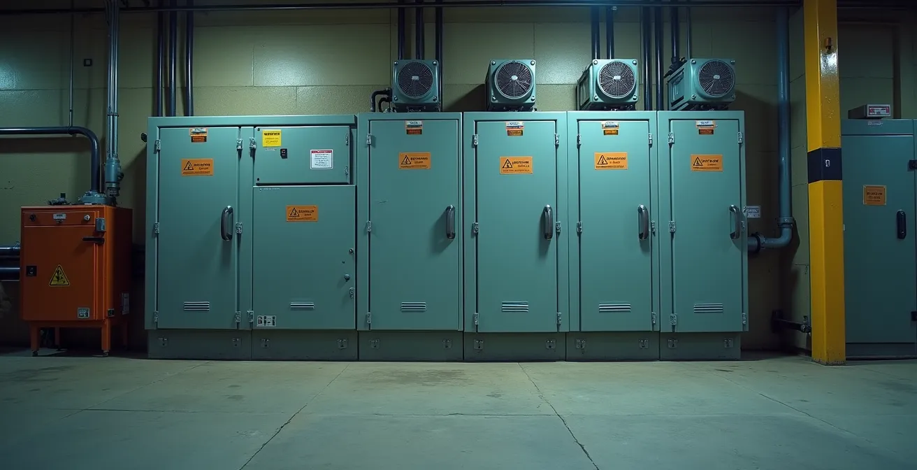
The air shimmers above the furnace, and another production run grinds to a halt. The HMI is frozen, and a PLC in a “cool” cabinet 50 metres away is throwing faults. As an electrical engineer in a UK foundry, this scene is an expensive, frustrating, and all-too-common reality. The usual advice rings hollow: you’ve already installed fans, you’ve bought “industrial-grade” gear, and you’re still fighting a losing battle against an invisible enemy. The heat. But what if the problem isn’t just the ambient temperature? What if the standard playbook is fundamentally flawed?
Most strategies focus on combating the number on the thermometer. This is a mistake. The true culprits are the secondary effects of heat that spec sheets conveniently omit. These are the hidden killers: thermal derating that strangles performance, dew point collisions that create internal condensation, and conductive metallic dust that turns your enclosures into a fire hazard. Relying on a component’s maximum operating temperature is like navigating a minefield with a tourist map; it ignores the real dangers on the ground.
This guide isn’t about buying more expensive equipment. It’s about mastering the physics of failure. We are not salespeople; we are specialists who build systems to survive hell. We will dissect the engineering principles that cause your electronics to fail in extreme heat and provide rugged, field-tested strategies tailored for the unique challenges of UK foundries, from post-Brexit compliance to the ever-present DSEAR regulations. We’ll give you the tools to move from reactive repairs to proactive, engineered resilience.
This article provides a detailed roadmap for protecting your critical systems. We will explore the science behind component failure, compare cooling technologies, analyse the true cost of ownership, and provide actionable protocols for managing environmental hazards and ensuring regulatory compliance in the UK.
Summary: A UK Engineer’s Field Manual for Electronics in Extreme Heat
- Why your standard PLCs are failing at 40°C despite rated specs?
- How to retrofit vortex coolers to control cabinets in dirty environments?
- Rugged industrial PCs vs Commercial tablets: is the £2k price difference justified?
- The condensation risk when moving tech from cold storage to hot floors
- How to monitor equipment health remotely to avoid entering hazardous zones?
- Why flour dust is just as dangerous as natural gas in confined spaces?
- How to recapture 70% of waste heat from your extraction system?
- ATEX Compliance in the UK: Defining Zones 0, 1, and 2 for Dust and Gas Safety
Why your standard PLCs are failing at 40°C despite rated specs?
Your PLC is rated to 60°C, yet it starts throwing inexplicable faults when the cabinet interior hits a mere 40°C. This isn’t a defective unit; it’s a predictable physical phenomenon called thermal derating. The maximum temperature on a spec sheet is a survival limit, not a performance guarantee. It’s the temperature at which the component won’t melt, but it says nothing about its ability to operate reliably. For every degree above a certain threshold, often as low as 40°C, the component’s processing capacity and lifespan begin to decrease significantly.
The core of the issue is that internal heat generation adds to the ambient temperature. A cabinet full of power supplies, drives, and processors can easily add 5-15°C to the internal temperature. So, on a 35°C summer day, your “cool” cabinet is already pushing 50°C inside, deep into the derating zone. According to industrial power supply specifications, this can trigger a 10-20% capacity reduction above 40°C internal temperature. This reduction manifests as slower processing, dropped data packets, and “phantom” faults that are impossible to diagnose because the component appears to be working within its operational limits.
Relying on passive ventilation or simple fans in a foundry is often futile. They can only ever achieve a temperature equal to the ambient air, which is already too hot and filled with conductive dust. A food processing facility facing similar issues found that even with fans, their PLCs failed at 45°C. Only by installing active refrigeration cooling, which could force the internal temperature below the 40°C derating threshold, did they achieve zero heat-related faults. The lesson is clear: you must engineer for an internal temperature below 40°C, regardless of what the spec sheet promises.
How to retrofit vortex coolers to control cabinets in dirty environments?
When fans are no longer sufficient, engineers often consider cabinet air conditioners. However, in the gritty, dusty environment of a foundry, A/C units with their compressors and filters can become a high-maintenance liability. A more robust, albeit less-known, alternative is the vortex cooler. This device has no moving parts, making it incredibly reliable in dirty conditions. It uses a standard compressed air supply, splitting it into hot and cold air streams via a vortex tube generator. The cold air is directed into the cabinet, while the hot air is exhausted, providing powerful, on-demand cooling.
The primary advantage of a vortex cooler is its immunity to the environment. Since it creates a positive pressure inside the enclosure, it actively prevents dust and debris from entering. This is a game-changer in a foundry where airborne metallic particles can clog A/C filters in hours and short-circuit electronics. The installation involves cutting a single hole for the cooler, typically on the cabinet top or side, and connecting a filtered compressed air line. Multi-stage filtration on the air intake is non-negotiable to remove oil, water, and particulates from the compressed air before it enters the vortex tube.
However, this technology is not a universal solution. Vortex coolers are notoriously noisy and consume a significant amount of expensive compressed air, making their operational costs much higher than a traditional A/C unit. The choice is a classic engineering trade-off between initial cost, maintenance resilience, and long-term running expenses. For a critical control panel in a horrifically dirty location where reliability is paramount, a vortex cooler is often the superior choice. For a larger cabinet in a cleaner area, a ruggedized A/C unit might be more economical.
The following table provides a stark comparison of the long-term financial implications, using typical UK industrial rates. It highlights that the decision goes far beyond the initial purchase price.
| Factor | Vortex Cooler | Cabinet A/C |
|---|---|---|
| Initial Cost | £800-1500 | £2000-4000 |
| Annual Energy Cost (UK rates) | £2400-3600 | £600-900 |
| Noise Level | 80-90 dBA | 55-65 dBA |
| Maintenance Frequency | Monthly filter changes | Quarterly service |
| Lifespan | 5-7 years | 10-15 years |
Rugged industrial PCs vs Commercial tablets: is the £2k price difference justified?
The temptation to replace a bulky, expensive industrial PC (IPC) with a sleek, cheap commercial tablet is strong. When an IPC costs £3,000 and a tablet is £1,000, the finance department sees an easy win. This is a dangerous and costly illusion. The price tag only tells a fraction of the story; the real metric is the Total Cost of Failure (TCF). A commercial device is built for an office, not for the thermal shock, vibration, and conductive dust of a foundry floor. Its failure is not a matter of ‘if’, but ‘when’.
As the Engineer Fix technical team states in their guide, the core difference is design intent. Their analysis highlights that “Industrial-rated devices must withstand significant temperature fluctuations, dust, and moisture for extended periods, ensuring mission-specific systems deliver continuous, error-free operation where failure is costly or dangerous.” A commercial tablet’s fanless design, intended for silence, becomes a death sentence in a foundry. With no way to dissipate heat, its processor throttles aggressively before failing completely. An IPC, by contrast, uses robust heat sinks, superior airflow management, and components rated for a wider temperature range, ensuring it maintains performance under thermal load.
Let’s run a quick, back-of-the-envelope TCF calculation. Assume the £3k IPC has an annual failure rate of 2% in foundry conditions, while the £1k tablet fails at a rate of 15%. A single failure incident costs £150 in engineering labour and, crucially, causes one hour of production downtime at a conservative cost of £1,000.
- Commercial Tablet Annual Cost: (£1000 / 2-year lifespan) + (15% x (£150 labour + £1000 downtime)) = £500 + £172.50 = £672.50 per year.
- Industrial PC Annual Cost: (£3000 / 7-year lifespan) + (2% x (£150 labour + £1000 downtime)) = £428 + £23 = £451 per year.
The rugged IPC is not only cheaper on an annual basis but, more importantly, it prevents an additional ~£150 of downtime-related costs each year. The initial £2,000 price difference is paid back in just over a year through sheer reliability. The price difference isn’t an expense; it’s insurance against failure.
The condensation risk when moving tech from cold storage to hot floors
One of the most insidious and least-understood threats to electronics in a foundry is not heat itself, but the transition between temperatures. Bringing a spare drive or control module from a cool, 10°C storage room directly onto a 35°C foundry floor creates a “dew point collision.” The cold surfaces of the electronics instantly cool the humid ambient air below its dew point, causing water to condense directly onto circuit boards, connectors, and power components. Powering up a device in this state is a guaranteed recipe for a short circuit and catastrophic, unrepairable failure.
This isn’t a theoretical risk; it’s a certainty governed by physics. The damage is often misdiagnosed as a random component failure, but the root cause was the thermal shock. This is particularly dangerous for Variable Frequency Drives (VFDs) and other high-power electronics where creepage distances are critical. A single drop of condensation in the wrong place can bridge a high-voltage gap, leading to an arc flash. The warranty will be void, and the cost of replacement is significant, all because of a simple, preventable process error.

To prevent this, a rigid acclimatisation protocol is not optional; it is mandatory. Any electronic equipment moving from a cold to a hot environment must be staged in an intermediate zone to allow its temperature to equalize slowly with the ambient air of its final destination. This prevents condensation from ever forming. This process must be documented and enforced without exception.
Your Action Plan: Foundry Acclimatisation Zone Protocol
- Designate a clean, dry, intermediate-temperature staging area (target 15-20°C).
- Log the arrival time and initial surface temperature of all incoming electronic equipment.
- Hold the equipment in the staging area for a minimum of 4 hours. Increase this to 6 hours for large drives (over 10kW) or densely packed components.
- Before power-up, perform an insulation resistance test with a Megger between phases and to ground to confirm the absence of moisture.
- Document the acclimatisation hold time and Megger results in the equipment log. This is critical for warranty compliance and fault analysis.
How to monitor equipment health remotely to avoid entering hazardous zones?
Entering a high-heat, high-noise, or potentially hazardous area on the foundry floor to perform a routine check on a control cabinet is inefficient and dangerous. The goal of a modern, resilient system is to eliminate the need for human presence wherever possible. This is achieved through robust remote monitoring using Industrial Internet of Things (IIoT) sensors. By instrumenting your critical cabinets, you can gain complete visibility of their health from the safety of a control room.
The most critical parameter to monitor is, of course, internal cabinet temperature. A simple, DIN-rail mounted temperature and humidity sensor can provide real-time data and historical trends. This data is invaluable. It’s not just about triggering an alarm when a threshold is breached; it’s about predictive maintenance. A gradual, steady rise in a cabinet’s baseline temperature over several weeks is a clear indicator that a cooling system’s filter is clogging or a fan is beginning to fail. This allows you to schedule maintenance during planned downtime, rather than reacting to an emergency shutdown.
This principle has been proven effective in other critical UK infrastructure. For instance, a case study on UK traffic control systems highlights the power of this approach. Industrial routers in roadside cabinets use remote monitoring to detect subtle temperature increases of just 0.5°C per week. This signifies filter clogging from traffic pollution, automatically generating a maintenance alert long before the internal electronics overheat. The implementation resulted in an 80% reduction in emergency site visits to hazardous roadside locations. The same strategy is directly applicable to the foundry, where IoT sensors for temperature, humidity, vibration, and door status can transform maintenance from a reactive firefight to a proactive, data-driven process, keeping your engineers safe and your production line running.
Why flour dust is just as dangerous as natural gas in confined spaces?
While the article’s title mentions flour, the real silent threat in a metal-casting environment is far more relevant: combustible and conductive metallic dust. In an industry where foundries can reach temperatures over 1425°C, the focus is often on the obvious heat hazards. However, fine airborne particles of metals like aluminium, magnesium, and even iron pose a triple threat that is often underestimated. This isn’t just a housekeeping issue; it’s a serious safety and operational risk governed by UK law.
First and foremost is the explosion risk. As the UK HSE regulatory framework makes clear, certain metallic dusts are highly combustible. The official guidance states, “Some metal dusts (e.g., Aluminium, Magnesium) are combustible and fall under DSEAR (Dangerous Substances and Explosive Atmospheres Regulations 2002), dictating the need for formal risk assessment and potentially certified equipment.” When suspended in air in the right concentration, these dusts can ignite with explosive force from a single spark, just like natural gas. This mandates a formal DSEAR assessment to classify hazardous zones and dictates the type of equipment that can be used within them.
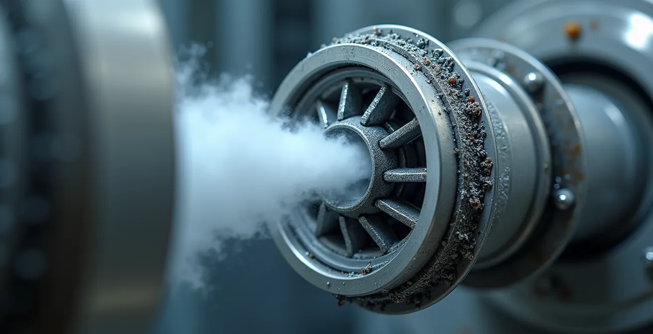
Second is the conductive threat. Unlike flour dust, metallic dust conducts electricity. When it inevitably infiltrates improperly sealed electronic enclosures, it settles on circuit boards. This coating can create unintended electrical pathways, or “creepage paths,” leading to short circuits and component failure. Finally, this dust blanket acts as an insulator, clogging the fins of heat sinks on processors, drives, and power supplies. This drastically reduces their ability to dissipate heat, accelerating thermal derating and leading to premature failure. A layer of dust can be the direct cause of a component overheating, even in a well-cooled cabinet. Ignoring metallic dust is ignoring a direct threat to both safety and production uptime.
How to recapture 70% of waste heat from your extraction system?
Foundries vent an enormous amount of energy into the atmosphere, particularly from processes like sand cooling and furnace extraction. This waste heat represents a significant operational cost and a missed opportunity. By implementing modern heat recovery technology, it’s possible to capture a large portion of this thermal energy and repurpose it, turning a liability into an asset that can simultaneously cut costs and improve electronics reliability.
A prime example is in foundry sand conditioning. After casting, green sand is incredibly hot, often over 120°C. Before it can be reused, it must be cooled. Traditional methods use evaporative cooling, which consumes water and vents steam. However, modern indirect plate heat exchangers can provide a much more elegant solution. These systems pass the hot sand over a series of plates while a cooling medium (like water) flows on the other side, absorbing the heat without direct contact. As reported by foundry cooling system manufacturers, these systems can reliably achieve a sand output temperature of 40°C from input temperatures of 120-140°C.
The captured heat, now stored in the water, can be used elsewhere in the facility. This is where the strategy becomes truly integrated. Instead of just heating offices, this “free” energy can be used to maintain the temperature of the acclimatisation zones we discussed earlier. This is the subject of a compelling case study.
Case Study: Integrated Heat Recovery for Electronics Protection
Waupaca Foundry, a major U.S. casting facility, implemented an indirect plate heat exchanger for its sand conditioning process. This not only provided precise temperature control for the sand, improving core quality, but also created a significant source of recovered heat. This hot water was then piped to maintain their equipment acclimatisation zones at an optimal, stable temperature. The result was a virtuous cycle: the system prevented condensation on new electronics while simultaneously reducing the facility’s overall heating costs by 33%.
This demonstrates a shift in thinking: waste heat isn’t something to be disposed of, but a resource to be managed. It creates a more resilient and economically efficient operation by using one process’s waste to solve another’s problem.
Key Takeaways
- Assume thermal derating will impact performance above 35°C ambient temperature; engineer for an internal cabinet temperature below 40°C.
- Enforce a mandatory, documented acclimatisation protocol for all electronics moving between temperature zones to prevent condensation-induced failure.
- Treat conductive metallic dust as a combustible and short-circuit threat requiring a formal DSEAR risk assessment and correctly IP-rated enclosures.
ATEX Compliance in the UK: Defining Zones 0, 1, and 2 for Dust and Gas Safety
Navigating hazardous area regulations in the UK has become more complex post-Brexit. While the principles of ATEX are still the foundation, UK-based facilities must now comply with DSEAR (Dangerous Substances and Explosive Atmospheres Regulations 2002) and, for new equipment in Great Britain, the UKEX certification scheme. For an engineer in a foundry, understanding this landscape is not just a matter of compliance; it’s a matter of law and safety. The first step is always a formal risk assessment.
Under DSEAR, the employer is legally required to assess the risks of fire and explosion. This involves identifying where combustible dusts or gases may be present and classifying these areas into zones based on the frequency and duration of the hazard’s presence:
- Zone 0 (Gas) or 20 (Dust): An area where an explosive atmosphere is present continuously or for long periods.
- Zone 1 (Gas) or 21 (Dust): An area where an explosive atmosphere is likely to occur in normal operation.
- Zone 2 (Gas) or 22 (Dust): An area where an explosive atmosphere is not likely to occur in normal operation, and if it does, will persist for only a short period.
Only a competent person can perform this assessment and create the legally required Explosion Protection Document (EPD). Based on this zoning, any electrical equipment installed must have the appropriate certification to ensure it cannot become an ignition source.
This is where the UKEX mark becomes critical. For new installations in England, Scotland, and Wales, equipment must be UKEX certified and carry the UKCA mark. While CE-marked ATEX equipment already in the supply chain can still be used for a limited time, any significant modification or new system requires a full assessment against UKEX standards. This has major implications for sourcing and specifying new control panels, sensors, and motors for zoned areas.
The following table from an Elmelin guide on foundry insulation summarises the post-Brexit requirements, which are crucial for any UK engineer to understand.
| Installation Type | Great Britain | Northern Ireland |
|---|---|---|
| New Equipment (2023+) | UKEX/UKCA Required | CE/ATEX Valid |
| Existing Stock | CE/ATEX Acceptable | CE/ATEX Valid |
| Replacement Parts | Match Original Cert | CE/ATEX Valid |
| System Modifications | Full UKEX Assessment | CE/ATEX Assessment |
Your Action Plan: DSEAR Risk Assessment Process for UK Foundries
- Commission a formal DSEAR risk assessment from a competent person or certified body recognised by the UK Health and Safety Executive (HSE).
- Create and maintain a site-specific Explosion Protection Document (EPD) containing the zone classifications and risk mitigation measures.
- Clearly map and label the defined hazardous zones (0, 1, 2 for gas; 20, 21, 22 for dust) on site plans.
- For all new equipment installed in Great Britain, verify it has valid UKEX certification and bears the UKCA mark.
- Check that all installations are compliant, paying close attention to the use of correctly rated cable glands, conduits, and intrinsic safety barriers for the specific zone.
Stop reacting to failures. Start engineering for survival. Use these principles to audit your own facility and build a system that won’t just endure the heat—it will master it. Begin by identifying your most frequent point of failure and apply the relevant strategy, whether it’s tackling thermal derating with active cooling or eliminating condensation risk with a simple, robust protocol.