
The belief that faster 3D printers are the key to sub-48-hour prototyping is a costly myth.
- True speed comes from systematically eliminating “operational drag”—the hidden delays in your data management, decision-making, and material selection processes.
- Achieving this velocity requires ruthless, front-loaded decisions on material properties and surface finish before a design ever reaches a machine.
Recommendation: Shift your focus from machine specs to your end-to-end process velocity. Audit your digital thread, from CAD file handling to final part validation, to identify and crush every source of delay.
For any UK-based R&D manager, the pressure to innovate faster is relentless. Your competitors, both domestic and global, are in a constant race to capture market share, and every week lost in the development cycle feels like an eternity. The common refrain is that rapid prototyping, particularly 3D printing, is the silver bullet. The market is flooded with advice to simply “buy a faster printer” or “adopt additive manufacturing” to shorten lead times. This advice, while well-intentioned, often misses the real source of the problem and leads to disappointing results.
The truth is, the bottleneck is rarely the machine’s print speed alone. The most significant delays are insidious, hiding in plain sight within your workflow: endless email chains with outdated CAD files, ambiguous material requirements leading to incorrect prints, and last-minute debates over surface finish. This is the costly friction of “operational drag”. This article will challenge the conventional wisdom. We will argue that achieving a true sub-48-hour CAD-to-physical-part cycle isn’t about raw machine speed. It’s about a strategic and ruthless elimination of process friction. It’s about adopting a mindset of front-loaded decision-making and creating an unbreakable digital thread from design to production.
Throughout this guide, we will dissect the critical decision points that make or break a rapid turnaround. We’ll explore how to choose materials that accurately mimic final production parts, decide between technologies for different prototype needs, and avoid common mistakes that render a prototype useless. Finally, we will outline a new way of working that makes a 48-hour sprint not just possible, but repeatable.
Summary: A Practical Guide to Sub-48-Hour Prototyping
- Why a 2-week delay in prototyping costs £15k in lost market opportunity?
- How to choose 3D printing filaments that mimic injection moulded ABS?
- SLA vs SLS: which technology delivers better surface finish for client demos?
- The shrinkage mistake that makes 3D printed prototypes useless for fit testing
- How to bridge the gap between a 3D print and a 500-unit pilot run?
- 3D printing vs CNC machining: which is faster for validating custom jigs?
- Why emailing CAD files is the root cause of expensive manufacturing errors?
- Cloud CAD Collaboration: How to Enable Remote Engineering Teams to Work in Sync?
Why a 2-week delay in prototyping costs £15k in lost market opportunity?
Every delay in the product development cycle has a real, quantifiable cost. A figure like £15,000 for a two-week delay isn’t just a scare tactic; it represents the tangible loss of first-mover advantage, missed sales windows, and the compounding cost of your engineering team’s time being tied up on a stalled project. In the competitive UK market, being second to launch can be the difference between capturing a dominant market share and fighting for scraps. The delay isn’t just lost time; it’s lost revenue and momentum.
This cost is a direct result of operational drag. It’s the time wasted waiting for a quote, the day lost because the wrong file version was sent to the print bureau, or the three days spent reprinting a part because the initial material choice was wrong. These small administrative frictions accumulate into significant, expensive delays. Reducing this cost isn’t about making your engineers work faster; it’s about making the process smarter.
Innovations in manufacturing technology, such as bound metal deposition which allows for complex metal parts to be created in-office, are designed specifically to crush these lead times. By removing the need to outsource to traditional, slow manufacturing services for metal prototypes, companies can iterate in days, not weeks. The core principle is universal: by bringing prototyping capabilities closer to the design team and streamlining the process, you directly attack the sources of delay and reclaim that lost market opportunity before it even vanishes.
Ultimately, viewing time as a critical resource, just like capital, forces a re-evaluation of every step in your prototyping workflow. Every hour saved is another hour ahead of the competition.
How to choose 3D printing filaments that mimic injection moulded ABS?
One of the most critical front-loaded decisions in rapid prototyping is material selection. A prototype that looks right but doesn’t behave like the final product is of limited use for functional testing. When your end product will be injection-moulded ABS, your goal is to find a 3D printing filament that offers the closest possible “prototype fidelity” in terms of strength, temperature resistance, and feel. Making the wrong choice leads to misleading test results and costly reprints.
Standard ABS is a common choice for FDM printing, but its tendency to warp and its need for a heated chamber can introduce delays. Fortunately, several alternative materials offer comparable or even superior properties with better printability. ASA (Acrylonitrile Styrene Acrylate), for instance, provides similar strength to ABS but with superior UV and temperature resistance, making it ideal for parts that will be tested outdoors. PETG offers excellent layer adhesion and tensile strength, though with lower temperature resistance. For applications demanding maximum performance, a PC-ABS (Polycarbonate-ABS) blend delivers exceptional strength and heat resistance, though it comes at a higher cost and can be more challenging to print.
This decision cannot be an afterthought. It must be made during the CAD phase, based on the specific validation requirements of the prototype. Is this a “looks-like” model for a meeting, or a “works-like” model for stress testing? Answering this question early prevents wasted machine time and ensures the feedback you get from the physical part is genuinely valuable.
The following comparison, based on data from industry suppliers, highlights the key trade-offs you need to consider. As shown in a technical analysis of CAD in prototyping, these material properties are central to successful outcomes.
| Material Type | Tensile Strength | Temperature Resistance | UK Availability | Cost per kg |
|---|---|---|---|---|
| Standard ABS | 40 MPa | 80-95°C | Wide | £20-30 |
| ASA | 45 MPa | 95-110°C | Moderate | £35-45 |
| PETG | 50 MPa | 70-80°C | Wide | £25-35 |
| PC-ABS Blend | 60 MPa | 110-125°C | Limited | £50-70 |
By treating material selection as a strategic choice rather than a logistical one, you eliminate a major source of rework and accelerate the journey to a viable design.
SLA vs SLS: which technology delivers better surface finish for client demos?
When a prototype is destined for a client presentation or a key stakeholder review, aesthetics matter. A rough, layer-lined part can subconsciously devalue the design in the eyes of a non-technical audience. This is where the concept of prototype fidelity extends to visual quality, and the choice between Stereolithography (SLA) and Selective Laser Sintering (SLS) becomes paramount. This is another front-loaded decision: the end-use of the prototype must dictate the technology.
For a visually stunning model with a smooth, almost injection-mould-quality surface finish, SLA is the undisputed winner. This technology uses a laser to cure liquid resin layer by layer, capable of achieving incredibly fine details and a layer resolution as low as 25 microns. The resulting parts are perfect for showcasing intricate designs, ergonomic shapes, and for use as master patterns for vacuum casting. The trade-off is that SLA parts require post-processing (washing in solvent and curing in UV light) and are generally more brittle than their SLS counterparts.
Conversely, SLS excels in producing functional, durable prototypes. It uses a laser to sinter powdered nylon, resulting in parts with excellent mechanical properties that are suitable for snap-fits, living hinges, and rigorous functional testing. However, the surface finish is inherently grainy and matte. While this is perfectly acceptable for internal engineering validation, it lacks the “wow factor” needed for a high-stakes client demonstration. The key advantage of SLS is that it requires no support structures, allowing for complex internal geometries to be printed with ease.
| Feature | SLA (Stereolithography) | SLS (Selective Laser Sintering) |
|---|---|---|
| Surface Finish | Smooth, high-resolution | Slightly grainy, matte |
| Layer Resolution | 25-100 microns | 60-120 microns |
| Post-Processing | Washing & curing required | Powder removal only |
| Material Strength | Moderate | High |
| Best For | Visual models, jewelry | Functional prototypes |
Therefore, the choice is clear: if the primary goal is to impress and persuade with a visually perfect model, choose SLA. If the goal is to test function and durability, SLS is the more practical and robust option.
The shrinkage mistake that makes 3D printed prototypes useless for fit testing
There is nothing more frustrating than waiting hours for a 3D print, only to discover it doesn’t fit its mating part. This common failure is often caused by a single, overlooked factor: material shrinkage. As thermoplastic materials cool from their extrusion temperature, they contract. If this shrinkage is not accounted for before printing, a part designed to be 100mm long might end up being 99.5mm. For a simple visual model, this is irrelevant. For a prototype intended for a precise fit-test, this renders it completely useless, wasting time, material, and momentum. This is a classic example of technical oversight causing significant operational drag.
The global rapid prototyping market is booming, with projections suggesting growth at a 20.49% CAGR from 2024 to 2034, but this growth is meaningless if the parts produced aren’t dimensionally accurate. Each material has a specific shrinkage rate, typically between 0.3% and 0.8% for common filaments like ABS and PETG. This factor must be compensated for in the CAD software *before* the file is sent to the slicer. Ignoring this step is a rookie mistake with professional consequences.
Furthermore, environmental conditions like ambient temperature and humidity in the workshop can influence the cooling rate and exacerbate shrinkage or warping. True precision requires a controlled process. To avoid this costly error, a pre-flight checklist is not just good practice; it’s essential for maintaining process velocity and ensuring the first print is the right print.
Your Pre-Print Shrinkage Compensation Checklist
- Verify Environment: Check that the workshop ambient temperature is stable (ideally 20-22°C) and humidity is within the 40-50% range to ensure consistent cooling.
- Consult Datasheet: Review the specific material datasheet provided by the manufacturer to find the exact shrinkage rate for the filament you are using.
- Apply CAD Compensation: Scale the part in your CAD model by the inverse of the shrinkage factor (e.g., scale by 100.5% for a 0.5% shrinkage rate) before exporting the STL file.
- Print Calibration Part: Before the main print, run a quick print of a small, dimensionally known calibration cube to verify that your compensation settings are producing accurate results.
- Document Conditions: Record the material batch number, print settings, and environmental conditions for each print to create a repeatable quality assurance process.
By integrating this discipline into your workflow, you transform 3D printing from a game of chance into a reliable engineering process.
How to bridge the gap between a 3D print and a 500-unit pilot run?
A successful 3D printed prototype is a major milestone, but it’s not the finish line. The next challenge is scaling up: how do you move from a single part to a 500-unit pilot run for wider testing, marketing samples, or an initial product launch? This “bridge” manufacturing phase is a common stumbling block. Hard tooling for injection moulding is too slow and expensive for this volume, while 3D printing 500 individual units is inefficient. The answer lies in intermediate tooling solutions that balance speed, cost, and quality.
One of the most effective bridge technologies is vacuum casting. This process uses a high-quality 3D printed master pattern (often made with SLA for its superb surface finish) to create a silicone mould. This soft mould can then produce 20-50 high-fidelity polyurethane parts that closely mimic the properties and finish of injection-moulded components. For a 500-unit run, you would simply create multiple silicone moulds from the single master pattern. This is a powerful way to leverage a CAD model for low-volume production without committing to expensive steel tools.
Engaging with the right partners is crucial for this step. The UK has a vibrant and growing ecosystem of specialised service bureaus. In fact, the UK rapid prototyping services sector comprises 223 businesses and is growing at 11.5% annually. These specialists have the expertise in soft tooling and vacuum casting to guide you through this transition efficiently.
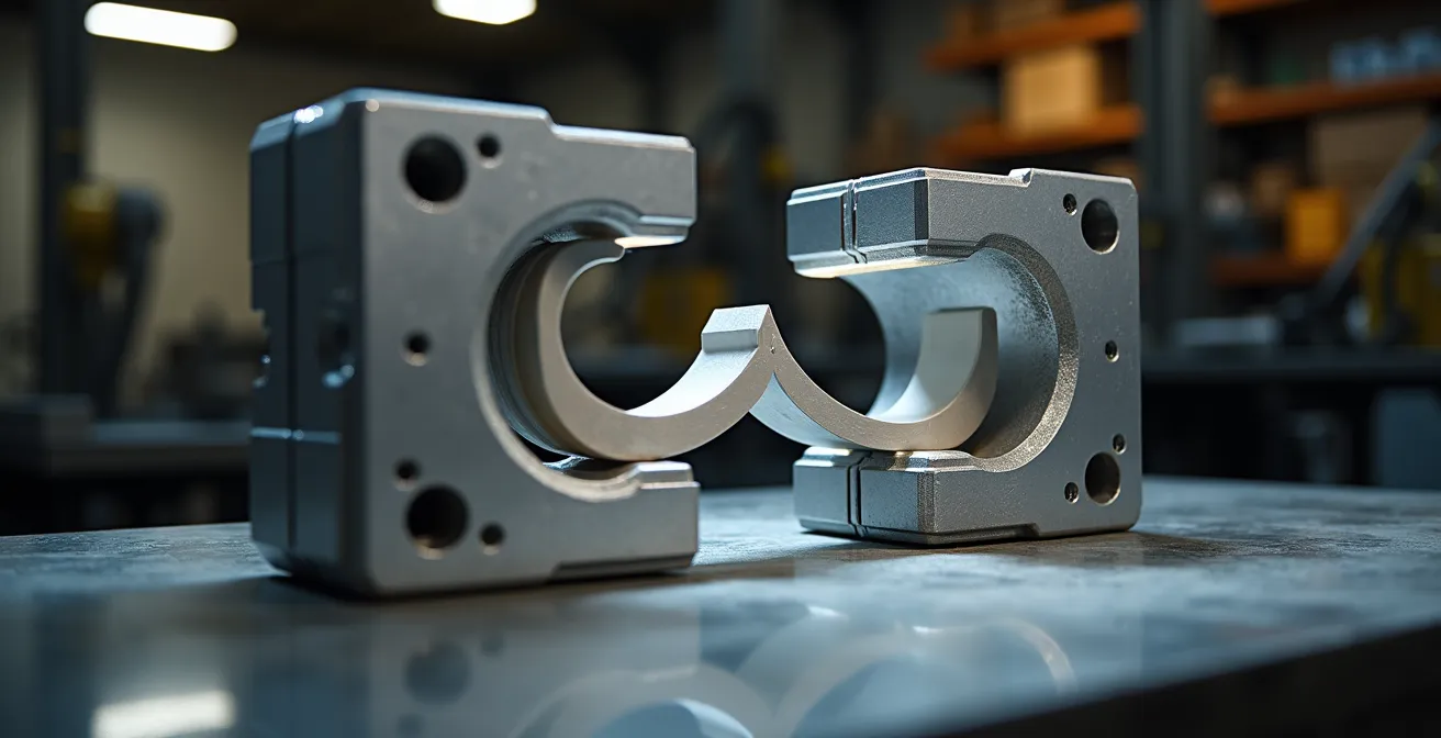
As the image above illustrates, this bridge tooling phase is the critical link between a single validated prototype and the confidence to move to mass production. It allows you to get real parts into the hands of users and stakeholders quickly, gathering invaluable feedback before making a six-figure investment in hard tooling. It is the final step in de-risking your product launch.
Choosing the right bridge manufacturing strategy is just as important as the initial prototyping technology, ensuring your project maintains momentum all the way to market.
3D printing vs CNC machining: which is faster for validating custom jigs?
The speed of iteration isn’t just for end-products; it’s equally critical for the custom tools, jigs, and fixtures that enable your assembly line. When you need to validate a new custom jig, the choice between 3D printing (FDM) and CNC machining comes down to one thing: total process velocity. It’s not about which machine runs faster, but which process gets a usable part in your hands quicker, from file export to final fit-check on the line.
For most custom jigs with moderate complexity, 3D printing is significantly faster in total turnaround. While the actual print time might be several hours, the setup time is minimal—often under 30 minutes to load a file and start the machine. This allows for near-instant production starts. You can design a jig in the morning and have a physical, testable part by the end of the day. The design flexibility of 3D printing also allows for the creation of complex, ergonomic shapes and internal channels that would be difficult or impossible to machine from a single block.
In contrast, CNC machining involves substantial setup time. It requires generating CAM toolpaths, setting up the workpiece, and selecting the right cutting tools, a process that can easily take 2-4 hours before any material is even cut. While the machining itself might be faster for a simple part (1-2 hours), the total turnaround is often longer. However, CNC machining’s key advantages are its ability to work with a vast range of materials (especially metals) and its superior precision and surface finish, which may be required for high-wear or high-tolerance fixtures.
In terms of cost, the difference is stark. A 3D printed jig might cost £20-£50 in material, whereas a one-off CNC machined equivalent could easily run from £100-£300 due to the skilled labour and setup involved. For rapid validation and iteration of custom work-holding, 3D printing offers an unbeatable combination of speed and low cost.
For R&D managers looking to optimize their production lines on the fly, having an in-house 3D printer dedicated to creating and testing jigs is a powerful tool for continuous improvement.
Key takeaways
- Focus on eliminating “operational drag” in your workflow; don’t just fixate on machine print speeds.
- Make critical decisions on materials, finish, and technology upfront to prevent costly rework and delays.
- Implement a robust “digital thread” for your CAD data to eradicate version control errors and ensure seamless data transfer.
Why emailing CAD files is the root cause of expensive manufacturing errors?
In the quest for 48-hour prototyping, the single greatest source of operational drag and catastrophic error is a seemingly innocuous process: emailing CAD files. Every time a designer attaches a `.STEP` or `.STL` file to an email with a subject line like “Final_Design_v2_use_this_one.stl”, you are introducing a massive risk into your workflow. This practice is the antithesis of a robust digital thread and is responsible for countless manufacturing mistakes, from producing the wrong version of a part to using incorrect design specifications.
The problems are manifold. There is no single source of truth; multiple versions of the “final” file exist across different inboxes. There is no audit trail to see who made changes and when. Permissions are non-existent, meaning anyone can forward or modify a file, leading to a loss of intellectual property control. This chaotic approach is a direct cause of delays and wasted resources. Manufacturing a complex part from an outdated file because of email confusion is an entirely preventable, and expensive, mistake.
The solution is to treat your CAD data with the same discipline as your financial data. This means implementing a centralized Product Data Management (PDM) or Product Lifecycle Management (PLM) system, even a lightweight, cloud-based one. As confirmed by foundational research on integrated product development, managing data centrally is a cornerstone of efficient engineering. A proper system ensures everyone—from the design engineer to the manufacturing partner—is working from the exact same file. It provides version control, logs every change, and manages user permissions.
Moving away from email as a file transfer system is the first, non-negotiable step toward building a true, high-velocity rapid prototyping workflow.
Cloud CAD Collaboration: How to Enable Remote Engineering Teams to Work in Sync?
Eliminating email attachments is the first step; embracing real-time cloud collaboration is the leap forward that makes a sub-48-hour cycle possible. With engineering teams often distributed, a centralized, cloud-based CAD/PLM platform becomes the digital backbone of your operation. It creates the seamless digital thread that connects your remote engineers, your in-house managers, and your external manufacturing partners into a single, cohesive unit.
Modern cloud platforms like Autodesk Fusion or Onshape are designed for this. They allow multiple engineers to work on the same master model simultaneously, with changes propagating instantly to everyone. Managers can review designs in a web browser, add markups and annotations in real-time, and grant approval without a single file ever being downloaded or emailed. This isn’t just a convenience; it’s a radical compression of the review and approval cycle, which is often a major source of delay.
Furthermore, the most advanced systems use APIs to connect directly to the quoting engines of 3D printing service bureaus. This means a manager can approve a design, and with a single click, the file is securely sent for an instant quote and order placement. This eliminates the entire manual process of exporting files, writing emails, and waiting for a response. It transforms the workflow from a series of discrete, delayed steps into a continuous, high-velocity flow. The following plan shows how this integration makes a 48-hour sprint a concrete reality.
Your 48-Hour CAD-to-Part Sprint Plan
- Day 1, 10:00: Engineering team finalizes the CAD design via a shared session on the cloud platform, ensuring all stakeholders are aligned.
- Day 1, 14:00: R&D Manager reviews the 3D model in-browser, using real-time annotation tools to request final tweaks or grant approval.
- Day 1, 15:00: Upon approval, the platform’s direct API integration sends the file to a preferred UK service bureau for an automated, instant quote.
- Day 1, 16:00: The order is confirmed and paid, and the part is nested into the bureau’s overnight 3D printing build queue.
- Day 2, 09:00: You receive an automated dispatch notification with a tracking number for the printed and cleaned part.
- Day 2, 15:00: The physical prototype is delivered to your facility, ready for fit testing and validation—well within the 48-hour window.
Stop accepting delays as the cost of innovation. It’s time to audit your process, eliminate the operational drag, and leverage cloud collaboration to reclaim your competitive edge. Start by mapping your current workflow today.