Achieving a 20% vehicle weight reduction with smart composites is not about simple material substitution, but about mastering the engineering trade-offs that unlock true performance gains and cost savings.
- The high stiffness-to-weight ratio of composites enables radical part consolidation, offering greater cost and efficiency benefits than weight reduction alone.
- Invisible manufacturing flaws like process-induced fiber waviness can catastrophically reduce component strength, making process control paramount.
- Lifecycle decisions, from choosing fire-retardant phenolic resins for rail to using Friction Stir Welding for battery trays, are critical for performance, safety, and sustainability.
Recommendation: Focus on Design for Manufacture (DfM) and Design for Disassembly (DfD) from the project’s inception to avoid costly downstream corrections and create genuinely sustainable, high-performance components.
As a design engineer in the transport sector, you are under constant pressure to make things lighter. The goal is clear: reduce vehicle mass to extend electric vehicle (EV) range or improve fuel efficiency. The go-to answer for the last decade has been a simple mantra: “replace steel with carbon fibre composites.” While this is true, this simplistic view overlooks the complex engineering reality. Focusing solely on the weight-saving number on a datasheet is a recipe for expensive prototypes that fail in production.
The real challenge isn’t *if* composites can reduce weight, but *how* to implement them effectively to improve durability, manage costs, and meet stringent industry standards. The transition from metal to smart composites introduces a new set of trade-offs and potential failure points that are often invisible to the untrained eye. What happens when your lightweight part fails to meet rail fire safety regulations? Or when a seemingly perfect component hides a microscopic manufacturing flaw that compromises its structural integrity? These are the questions that separate a successful lightweighting program from a failed one.
This article moves beyond the “lighter and stronger” platitudes. We will dissect the critical, often-overlooked engineering decisions that determine success. We’ll explore why stiffness is more important than weight, how to integrate sensors for structural health monitoring, how to select the right resin for fire safety, and how to design parts that can actually be manufactured and recycled. This is your guide to navigating the true complexities of smart composites to deliver on the promise of a more efficient and durable future for transport.
This in-depth analysis will equip you with the practical knowledge to make informed decisions at every stage of the design and manufacturing process. The following sections break down the key challenges and solutions you will face when engineering with advanced composite materials.
Summary: Smart Composites in Transport: Engineering Beyond a 20% Weight Reduction for EV Range
- Why replacing steel with carbon fibre isn’t just about weight, but stiffness?
- How to embed strain gauges inside composite layers during layup?
- Epoxy vs Phenolic resins: which is required for rail fire safety standards?
- The manufacturing flaw that causes invisible structural weakness in composites
- How to design composite parts that can actually be recycled in the UK?
- Why adapting standard brackets adds £20,000/year in labour costs?
- Why TIG welding warps your battery trays and ruins seal integrity?
- Friction Stir Welding: Joining Aluminium and Copper for EV Battery Efficiency
Why replacing steel with carbon fibre isn’t just about weight, but stiffness?
The initial conversation around carbon fibre composites invariably starts with weight. It’s a compelling figure; manufacturing analysis reveals that carbon fiber automobile bodies can be up to 70% lighter than their steel counterparts. However, for a design engineer, the most transformative property of carbon fibre is not its low density, but its exceptional stiffness-to-weight ratio. High stiffness allows you to design parts that resist deformation under load using significantly less material. This property is the true enabler of revolutionary design changes, moving far beyond simple one-to-one material substitution.
When a component is sufficiently stiff, you can integrate multiple functions into a single, complex shape. This is the principle of part consolidation. Instead of bolting together ten different stamped steel pieces to form a chassis component, you can design one molded composite part that does the job of all ten. This drastically reduces assembly time, labour costs, tolerance stack-up issues, and the number of potential failure points (like welds and fasteners). The focus shifts from merely making a part lighter to re-imagining the entire assembly for manufacturing efficiency.
To truly understand this concept, it’s useful to visualize how the material’s internal structure contributes to its overall rigidity. The layered nature of composites allows for precise engineering of performance characteristics.
As this cross-section illustrates, the orientation of the carbon fibres within the matrix can be tailored to handle specific load paths. This level of design freedom is impossible with isotropic materials like steel or aluminium. The BMW i3 provides a landmark example of this philosophy in action.
Case Study: The BMW i3 Life Module
The entire passenger cabin of the BMW i3 is a “Life Module” constructed from approximately 150 carbon-fibre composite components. This approach achieved a 50% weight reduction compared to an equivalent steel structure and 30% against aluminium. More importantly, as detailed in an analysis of composites in automotive, this stiffness-driven design enabled a radical part consolidation that halved the conventional production time. It demonstrates that designing for stiffness, not just weight, is what unlocks the most significant economic and performance advantages of composites.
How to embed strain gauges inside composite layers during layup?
A key advantage of composites is the ability to create “smart” structures with integrated sensing capabilities. Embedding sensors like strain gauges or Fibre Bragg Gratings (FBGs) during the manufacturing layup process allows you to monitor the health of a component in real-time, a practice known as Structural Health Monitoring (SHM). This transforms a passive component into an active data source, providing invaluable insights into stress, fatigue, and potential damage throughout its service life. Research confirms that smart composites with integrated SHM capabilities are a rapidly emerging field, offering self-sensing and adaptability.
However, the process of embedding these sensors is not trivial. If done incorrectly, the sensor itself or its wiring can introduce a weakness into the composite structure. A poorly placed sensor can create a resin-rich pocket—an area with excess resin and no fibre reinforcement—or it can disrupt fibre alignment, leading to local delamination under load. The goal is to integrate the sensor so that it becomes a seamless part of the laminate, without compromising the very structural integrity it is meant to monitor.
Careful management of the lead-out wires is equally critical. These wires must be routed through the laminate and out of the part without creating a pathway for moisture ingress or a point of stress concentration. This requires meticulous planning during the design phase, considering wire insulation, orientation, and strain relief. Following a clear, systematic process is essential for success. The following checklist outlines the core stages for successfully integrating sensors into a composite component.
Action Plan: Embedding Sensors in a Composite Layup
- Sensor Selection: Select the appropriate sensor type (e.g., foil gauges for surface strain, Fibre Bragg Gratings for internal monitoring) based on the expected loading conditions and environmental factors.
- Strategic Positioning: During the layup process, carefully position sensors in critical stress areas, ensuring they are placed parallel to fibres and away from edges to avoid creating resin-rich pockets or causing local delamination.
- Wire Management: Plan the lead-out wire routing meticulously. Use proper insulation, control the orientation to minimize laminate disruption, and incorporate strain relief where the wire exits the part.
- Baseline Data Capture: Establish a data capture system to record sensor readings during the autoclave curing process. This provides a crucial baseline of residual stress locked into the part post-manufacturing.
- System Implementation: Implement the real-time monitoring hardware and software required to acquire, process, and interpret the continuous stream of data from the embedded sensors throughout the component’s operational life.
Epoxy vs Phenolic resins: which is required for rail fire safety standards?
While carbon fibre provides the strength, the resin matrix is what binds the fibres together, defines the processing characteristics, and critically, dictates the component’s response to fire. For a design engineer in the rail sector, this is not a minor detail; it is a primary design constraint governed by stringent standards like EN 45545. Choosing the wrong resin system can lead to a part that is structurally sound but fails certification due to poor fire, smoke, and toxicity (FST) performance. The two most common thermoset options, epoxy and phenolic resins, have fundamentally different behaviours in a fire.
Standard epoxy resins, while offering excellent mechanical properties and ease of processing, tend to combust in a fire, releasing heat, smoke, and toxic fumes. While modified FST-rated epoxies exist, they rely on additives to improve their performance. Phenolic resins, by contrast, have an inherently superior fire resistance. When exposed to extreme heat, their chemical structure promotes the formation of a stable, insulating char layer. This char acts as a thermal barrier, protecting the underlying composite structure and dramatically reducing the release of heat and smoke.
However, this superior FST performance comes with processing challenges. The curing reaction for phenolic resins releases water vapour, which can create voids and porosity in the laminate if not managed correctly. They are also more brittle than epoxies. As an expert in self-healing composites highlights, standard epoxy resins maintain thermal stability up to 200°C and can be formulated for high toughness, but phenolics excel in fire scenarios. An authoritative review from the Smart Composite Materials Research Team notes:
Epoxy resins maintain thermal stability with a high thermal decomposition temperature even at 200°C and have demonstrated self-healing effectiveness of over 90% when used in bulk materials.
– Smart Composite Materials Research Team, Smart Composite Materials with Self-Healing Properties Review
This data underscores the excellent thermal performance of epoxies in normal operating conditions. However, for applications demanding strict fire safety compliance, the choice is more nuanced, as the following comparison shows.
| Property | Phenolic Resins | Epoxy Resins | Modified FST-Rated Epoxy |
|---|---|---|---|
| Fire Resistance Mechanism | Char formation as insulating barrier | Standard combustion behavior | Enhanced with FST additives |
| Processing Difficulty | High (water vapor release, brittleness) | Low (easy processing) | Moderate |
| Thermal Stability | Excellent (>200°C) | Good (up to 200°C) | Good-Excellent |
| EN 45545 Compliance | Full compliance | Limited | Specific hazard levels |
| Manufacturing Cost | Higher | Lower | Moderate |
The manufacturing flaw that causes invisible structural weakness in composites
One of the most dangerous aspects of composite manufacturing is the potential for process-induced defects that are invisible to the naked eye but can catastrophically reduce a part’s strength. Unlike in metals where a crack is often visible, a critical flaw in a composite can be hidden within the laminate. The most notorious of these is in-plane fibre waviness or undulation. This defect occurs when fibres, which should be perfectly straight and aligned to carry the load, develop subtle, microscopic waves or wrinkles within a ply.
This flaw is a common side effect of automated manufacturing processes like Automated Fiber Placement (AFP). While AFP is designed to increase precision and speed, using an improper steering radius to lay down material on a complex curve, or applying incorrect compaction pressure, can force the fibres to buckle slightly. The result is a component that passes visual inspection and may even pass basic dimensional checks, but its compressive strength can be drastically reduced. Under compression, the wavy fibres will try to straighten out, pushing the layers apart and leading to premature delamination and failure at a fraction of the designed load capacity.
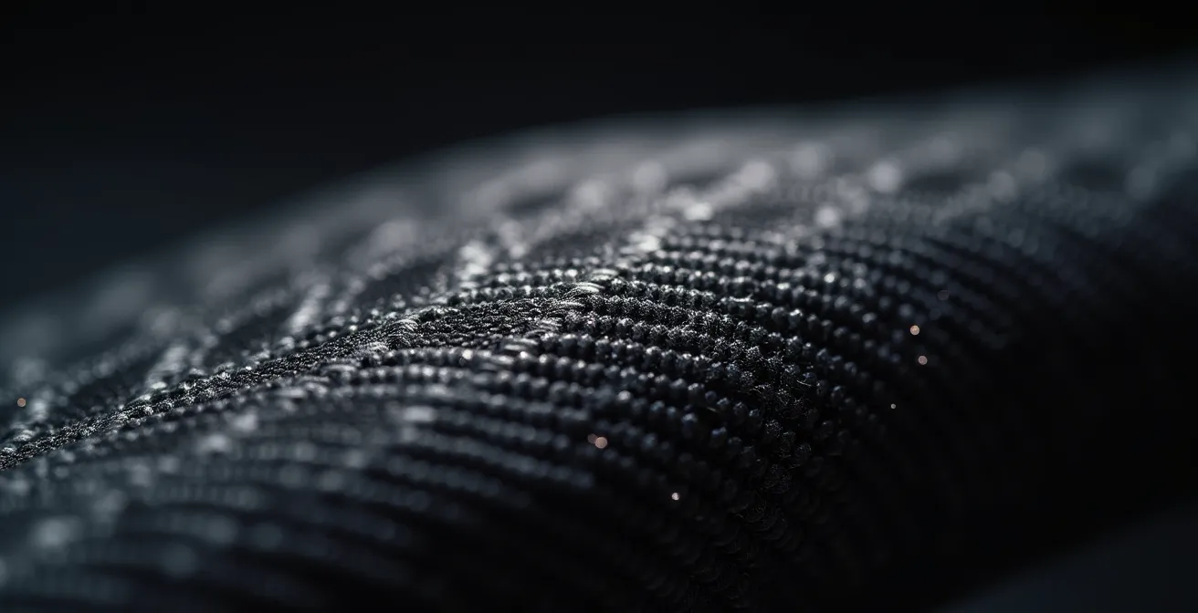
The abstract nature of this defect makes it difficult to detect without advanced non-destructive testing (NDT) methods. The image below provides a conceptual visualization of how these subtle distortions can hide within the material’s structure.

As the visual suggests, the waviness can be a subtle disruption deep within the laminate. The challenge is that traditional manufacturing processes often involve significant manual labour, which itself introduces variability. As one analysis of smart composite manufacturing points out, this complexity can lead to inconsistencies in quality. Automation is the solution, but only if the process is perfectly controlled to prevent these hidden defects.
The Challenge of In-Plane Fiber Waviness in AFP
Traditional composite manufacturing’s reliance on manual labor is prone to quality inconsistencies and long production times. Automated systems like AFP are the solution, but they introduce their own unique failure modes. When an AFP machine is programmed with a steering radius that is too tight for the material width or with insufficient compaction pressure, it can induce microscopic fiber undulations within the laminate. This seemingly minor imperfection is a critical flaw. It creates an internal stress point that drastically reduces the material’s compressive strength, creating a hidden weakness that can lead to unexpected structural failure under operational loads.
How to design composite parts that can actually be recycled in the UK?
As the transport sector pushes towards greater sustainability, the end-of-life treatment of composite materials has become a major engineering challenge. With environmental analysis showing that transportation accounts for 29% of EU greenhouse gas emissions, designing for recyclability is no longer optional. Traditional thermoset composites, bonded with permanent adhesives, are notoriously difficult to recycle. They often end up in landfill, negating some of the environmental benefits gained from lightweighting. To create truly sustainable components, you must adopt a Design for Disassembly (DfD) philosophy from the very beginning of the design process.
The core principle of DfD is to plan for the part’s end-of-life separation. This means making conscious choices about materials and joining methods. The first major decision is the matrix material. Shifting from a thermoset matrix (like epoxy) to a thermoplastic one (like PEEK or PEKK) is the single most impactful choice. Thermoplastics can be melted and reformed, making them mechanically recyclable in a way that cross-linked thermosets are not. For thermoset parts, the main recovery method is pyrolysis, which thermally decomposes the resin to recover the valuable carbon fibres. However, this process is sensitive to contamination, so avoiding certain additives and coatings is crucial.
Joining methods are the next critical consideration. Instead of using permanent structural adhesives, you should specify reversible bonding agents or mechanical fastening techniques where possible. Integrating co-cured thermoplastic inserts into a thermoset part can also create a designed failure point, allowing for easier separation of components at end-of-life. Finally, creating a digital “Material Passport” for each component, linked via a serial number, provides recyclers with a precise list of all constituent materials, enabling efficient and effective recovery.
Here are key strategies to incorporate into your design workflow:
- Favour Thermoplastics: Prioritize the use of a thermoplastic matrix (e.g., PEEK, PEI) over a thermoset one to enable mechanical recycling through remelting and reforming.
- Reversible Joining: Use reversible bonding agents or mechanical fasteners instead of permanent adhesives, particularly for multi-material assemblies.
- Smart Inserts: Implement co-cured thermoplastic inserts or localized material changes to create predetermined breaking points that facilitate easier separation of different materials at end-of-life.
- Avoid Contaminants: When using thermosets destined for pyrolysis, avoid contaminants like certain fillers or coatings that can disrupt the chemical recovery of the carbon fibres.
- Digital Material Passport: Create and link a digital record to each part’s serial number, detailing all constituent materials, resins, and additives to inform and streamline the recycling process.
Why adapting standard brackets adds £20,000/year in labour costs?
A common but costly mistake in lightweighting projects is the attempt to adapt existing standard metal parts for new applications, particularly for small components like brackets and fixtures. The thinking is often that modifying an off-the-shelf steel bracket is cheaper and faster than designing a new composite part from scratch. In reality, this approach introduces a cascade of hidden costs that accumulate rapidly. The process of manually adapting a standard part—cutting, drilling, shimming—is labour-intensive and creates a significant bottleneck in a streamlined production flow.
Each adaptation requires bespoke quality checks, potential modification of assembly jigs, and introduces variability that is the enemy of modern manufacturing. This “stop-start” disruption adds up. For a medium-volume production line, the cumulative cost of this additional manual labour, process interruption, and quality control can easily reach £20,000 or more per year for a single component type. In contrast, a purpose-designed composite part is engineered for its specific application. It arrives ready-to-install, requires no manual adaptation, and fits seamlessly into a continuous production flow with standard quality checks.
The business case for purpose-designed composites becomes undeniable when you analyze the total cost of ownership, not just the upfront part cost. The Ford Shelby GT350 Mustang’s grill reinforcement provides a powerful example of this principle.
Cost-Benefit Analysis: Ford Shelby GT350 Composite Reinforcement
In a partnership between BASF, Magna, and Ford, a carbon-fibre composite grill opening reinforcement was developed for the Shelby GT350. This purpose-designed component was 24% lighter than the traditional multi-piece steel assembly it replaced. The key benefit, however, was in manufacturing. By creating a single, integrated composite part, it eliminated the need for costly adaptation and assembly of multiple metal pieces, demonstrating how a proper Design for Manufacture (DfM) approach with composites can drastically reduce hidden production costs.
The following table breaks down the hidden costs associated with adapting standard parts versus the streamlined process of using a component designed for its purpose.
| Cost Factor | Adapted Steel Bracket | Purpose-Designed Composite |
|---|---|---|
| Direct Labour | High (manual adaptation required) | Low (ready-to-install) |
| Jig Modification | Required for each variant | Not required |
| Quality Checks | Bespoke inspection needed | Standard process |
| Production Flow | Stop-start disruption | Continuous flow |
| Assembly Steps | Multiple (drilling, shimming) | Single integrated part |
| Annual Cost Impact | £20,000 additional | Baseline cost |
Why TIG welding warps your battery trays and ruins seal integrity?
As EV design evolves, the battery enclosure has become a highly engineered, structural component. These trays, often made from lightweight aluminium alloys, must not only protect the battery cells but also maintain perfect dimensional stability to ensure the integrity of environmental seals against water and dust ingress. A common manufacturing choice for joining aluminium sections is Tungsten Inert Gas (TIG) welding. However, TIG is a high heat-input process, and this creates a significant problem: thermal distortion.
When you apply intense, localized heat with a TIG welder, you create a steep thermal gradient between the weld zone and the surrounding cold metal. As the weld pool cools and contracts, it pulls on the adjacent material, causing it to warp and twist. For a large, flat component like a battery tray, this distortion can be significant, making it impossible to achieve the tight tolerances required for effective sealing. A warped sealing flange can create gaps that compromise the enclosure’s IP rating, leading to catastrophic failure if moisture reaches the high-voltage components inside.
The solution is to move away from high heat-input processes and adopt alternative joining technologies that minimize the thermal gradient. The goal is to create a strong mechanical bond without introducing the destructive thermal stresses that cause warping. Each alternative comes with its own trade-offs in terms of cycle time, equipment cost, and joint strength, but all offer superior dimensional control compared to TIG welding.
Here are several low heat-input alternatives you should consider for assembling aluminium battery enclosures:
- Friction Stir Welding (FSW): A solid-state process that uses a rotating tool to plasticize and mix the metal without melting it. This creates a high-strength joint with minimal heat input and virtually no distortion.
- Laser Welding: Uses a highly concentrated beam of light to create a narrow, deep weld with a very small heat-affected zone, significantly reducing overall part distortion compared to TIG.
- Structural Adhesives: Modern epoxy and polyurethane adhesives can create bonds that are as strong or stronger than welds. This is a zero heat-input process that completely eliminates thermal distortion and can also help with vibration damping.
- Cycle Time vs. Distortion Trade-off: You must evaluate the trade-offs. For instance, FSW may have a longer cycle time than laser welding but offers superior joint properties for certain alloys.
- Joint Strength vs. Thermal Management: Evaluate the required joint strength against the absolute need to maintain dimensional tolerances for sealing. For many applications, adhesives provide more than enough strength while guaranteeing a perfect seal.
Key Takeaways
- Stiffness over Weight: The primary advantage of carbon fibre is its stiffness-to-weight ratio, which enables part consolidation, reducing assembly costs and complexity—a far greater benefit than simple weight reduction.
- Process Control is Paramount: Invisible, process-induced manufacturing defects like fiber waviness can negate all design benefits. Robust quality control and a deep understanding of manufacturing parameters are non-negotiable.
- Design for the Entire Lifecycle: Material choices, such as phenolic resins for fire safety or thermoplastics for recyclability, are critical design decisions that impact certification, safety, and end-of-life sustainability.
Friction Stir Welding: Joining Aluminium and Copper for EV Battery Efficiency
Having explored the challenges of material selection and manufacturing, the final frontier for optimizing transport components lies in joining dissimilar materials effectively. Nowhere is this more critical than inside the EV battery pack itself. For maximum efficiency, you need to create a low-resistance electrical connection between aluminium busbars and copper battery terminals. Traditional fusion welding methods are simply not viable for this task, as the two metals form brittle intermetallic compounds when melted together, leading to a weak and unreliable joint.
This is where Friction Stir Welding (FSW) becomes a game-changing technology. As a solid-state process, FSW joins the materials below their melting point. A specialized rotating tool plasticizes and mechanically intermixes the aluminium and copper, creating a strong, forged bond without the formation of brittle phases. This results in a joint with exceptionally low electrical resistance, which is critical for minimizing heat generation and maximizing battery efficiency and lifespan. Every milliohm of resistance saved is a watt of power that isn’t wasted as heat.
This level of thermal management is a core principle of EV design. As an analysis of composites in EVs points out, composite materials themselves are often engineered with specific thermal properties to help maintain the battery’s optimal operating temperature. FSW complements this perfectly by ensuring the connections *within* the battery pack are not a source of unwanted heat. The ability to create clean, strong, and highly conductive joints between aluminium and copper is a key enabler for building more powerful, efficient, and reliable battery systems.
FSW for Thermal Management in EV Batteries
Effective thermal management is crucial for EV battery performance and safety, as the cells must be kept within a narrow optimal temperature range. While composite enclosures with tailored thermal conductivity help dissipate heat to the environment, the joints inside the pack can be a major source of heat generation. FSW joints between aluminium and copper components are critical for reducing electrical resistance at these connection points. By minimizing resistive heating, FSW directly contributes to the battery’s overall thermal stability and operational efficiency, making it an essential technology for high-performance EV manufacturing.
To truly leverage the power of smart composites, the next logical step is to re-evaluate your current component designs not as one-to-one replacements, but as opportunities for radical part consolidation and the integration of advanced joining techniques like FSW. Start by identifying a multi-piece metal assembly and challenge your team to redesign it as a single, elegant composite solution.