For automotive engineers, traditional fusion welding is the primary source of thermal distortion, compromising the hermetic seal and structural integrity of EV battery trays. Friction Stir Welding (FSW) offers a definitive solution.
- FSW is a solid-state process that joins metals below their melting point, eliminating warpage and the Heat-Affected Zone (HAZ) degradation common in TIG/MIG welding.
- It produces defect-free, high-strength joints between dissimilar metals like aluminium and copper, crucial for achieving both mechanical robustness and electrical conductivity.
Recommendation: Evaluate FSW not as a mere alternative, but as a strategic process to de-risk production, improve battery pack safety, and eliminate costly post-weld corrective operations.
As an automotive engineer, your primary challenge in designing EV battery enclosures is a balancing act. The tray must be lightweight to maximize range, structurally robust to protect against impact, and perfectly sealed to guarantee an IP67 or higher rating against water and dust ingress. The widespread use of multi-material designs, particularly joining aluminium extruded profiles to copper busbars, adds another layer of complexity. Can you achieve high-speed, high-strength joins without compromising the material’s inherent properties?
The conventional answer often lies in fusion welding processes like TIG or laser welding. However, these methods introduce a significant variable: intense heat. This heat creates a weak, distorted Heat-Affected Zone (HAZ) that can undermine the entire design. The metallurgical headache of warpage, reduced strength, and potential for defects directly threatens the flatness required for a hermetic seal. This is not just a cosmetic issue; it’s a fundamental safety and reliability problem.
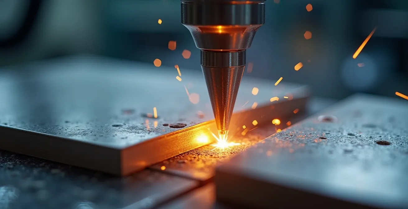
But what if the solution wasn’t to better manage the heat, but to eliminate it as the primary joining mechanism? This is the core principle of Friction Stir Welding (FSW). As a solid-state joining technology, FSW forges metals together below their melting point, preserving their original temper and strength. It’s not just a different way to weld; it’s a different way to think about metallurgical integrity for critical components.
This article moves beyond the textbook definitions to provide a specialist’s view on why FSW is the definitive answer to the aluminium-copper joining challenge in EV battery trays. We will dissect the failures of traditional methods, detail the validation process for FSW joints, compare its performance on key production metrics, and explore the tooling and automation that make it a scalable, industrial solution.
This in-depth analysis will equip you with the technical understanding needed to assess and implement this transformative technology. Explore the sections below to understand how FSW directly solves the engineering trade-offs you face every day.
Summary: A Specialist’s Guide to FSW for EV Battery Enclosures
- Why TIG welding warps your battery trays and ruins seal integrity?
- How to validate FSW joints for automotive crash safety standards?
- FSW vs Laser welding: which is faster for long linear seams?
- The ‘exit hole’ defect in FSW and how retractable pin tools solve it
- How to select tool materials to weld 5km of joint before replacement?
- Why replacing steel with carbon fibre isn’t just about weight, but stiffness?
- Solid-state vs MIG: which produces a ‘machined-look’ finish without grinding?
- Smart Composites in Transport: Reducing Vehicle Weight by 20% to Boost EV Range
Why TIG welding warps your battery trays and ruins seal integrity?
The fundamental problem with Tungsten Inert Gas (TIG) and other fusion welding processes is the introduction of extreme, localized heat. When you melt aluminium alloys to join them, you create a wide Heat-Affected Zone (HAZ). Within this zone, the carefully engineered temper of the base material is destroyed. The material re-solidifies with a coarser grain structure, leading to a significant loss of mechanical properties. This isn’t a minor issue; it’s a catastrophic degradation of the material’s designed strength and hardness.
This thermal damage is quantifiable. For high-performance aluminium alloys used in battery trays, research confirms that TIG welding can cause a drop to 53-60HV hardness in the HAZ, compared to a base material hardness of 90HV. This softened zone becomes the weakest link in the structure, prone to failure under mechanical stress or vibration. Furthermore, the intense heat and subsequent rapid cooling induce residual stresses, causing the defining problem for battery enclosures: warpage and distortion. The long, flat sealing surfaces required for gaskets are compromised, making a reliable, hermetic seal nearly impossible to achieve without extensive and costly post-weld machining.
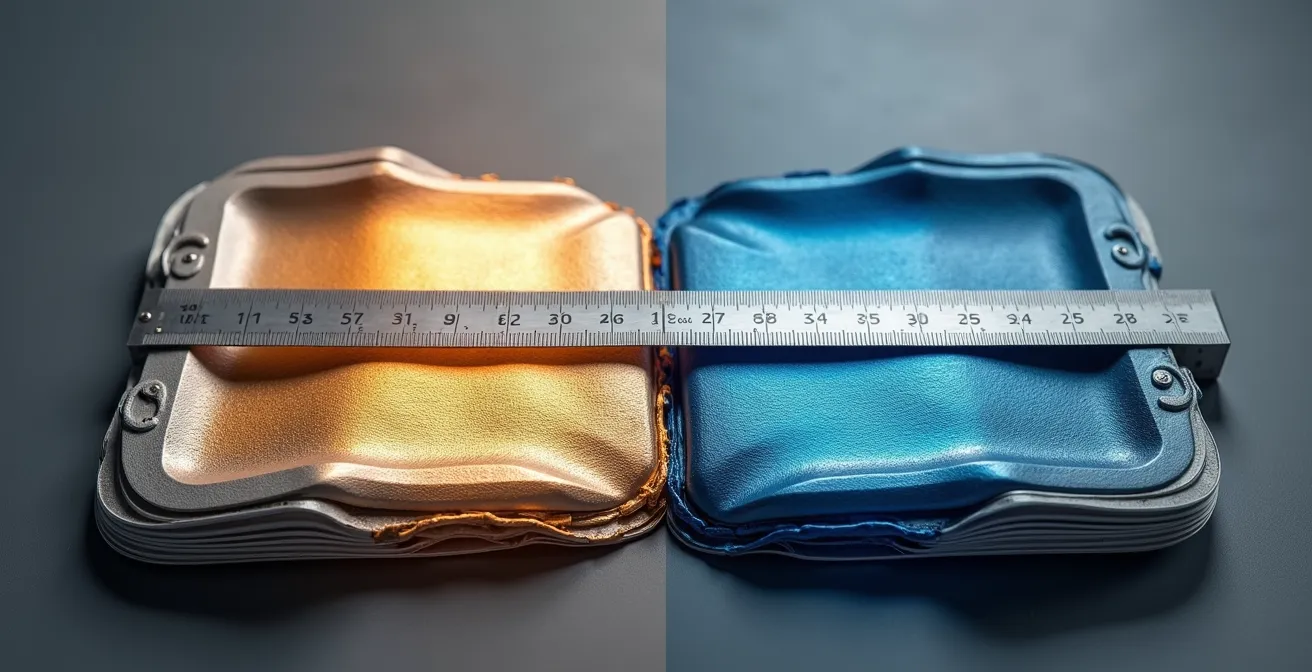
As shown in the visualization, this distortion isn’t uniform; it creates unpredictable peaks and valleys along the seam. This directly compromises the ability to achieve the consistent compression needed for an IP67 or IP68-rated seal. In essence, by using a fusion process like TIG, you are actively undermining the two most critical functions of the battery tray: structural integrity and environmental protection. The process itself becomes the primary source of defects.
How to validate FSW joints for automotive crash safety standards?
Validation is non-negotiable in automotive engineering. Moving to Friction Stir Welding requires a clear, data-driven process to prove its superiority and compliance with stringent safety standards. Unlike fusion welds, which are assessed for defects like porosity and cracking, FSW joint validation focuses on confirming the integrity of the solid-state bond and its mechanical performance relative to the parent material. The goal is to demonstrate that the joint is not the weakest point in the assembly.
A key metric is joint efficiency—the ultimate tensile strength of the weld as a percentage of the base material’s strength. FSW consistently delivers exceptional results here. Even at high production speeds, testing demonstrates FSW can achieve over 71% of base material strength at 4.0 m/min. This high efficiency ensures the battery tray maintains its structural role during a crash event, absorbing and distributing energy as designed, without catastrophic joint failure. This predictable performance is a stark contrast to the variable, often brittle nature of fusion welds in the HAZ.
For an engineer, this means implementing a rigorous testing protocol. The process goes beyond simple visual inspection and requires a multi-faceted approach to characterize the joint’s metallurgical and mechanical properties fully. These tests provide the empirical data needed to certify the component for automotive use.
Action Plan: FSW Joint Validation Protocol
- Cross-Sectional Analysis: Prepare and etch a sample of the weld to microscopically inspect for the absence of porosity, voids, or incomplete penetration, ensuring a continuous and hermetic sealing line.
- Tensile Testing: Conduct tensile tests according to ISO standards (e.g., ISO 25239) to quantify the joint’s ultimate tensile strength (UTS), yield strength, and elongation, directly calculating the joint efficiency.
- S-Bending Test: Evaluate the weld’s ductility and its ability to absorb deformation without fracturing. This test is critical for assessing performance in crash scenarios where significant plastic deformation occurs.
- Hardness Mapping: Perform a micro-hardness traverse (e.g., Vickers) across the weld nugget, thermo-mechanically affected zone (TMAZ), and HAZ to confirm the absence of significant softening compared to fusion processes.
- Visual Inspection: Examine the weld surface for excessive flash or surface imperfections, which can indicate incorrect tool pressure or wear, and confirm the consistency of the weld bead along its entire length.
FSW vs Laser welding: which is faster for long linear seams?
When it comes to high-volume production of EV battery trays, cycle time is a critical cost driver. Both Friction Stir Welding and laser welding are often considered high-speed alternatives to slower processes like TIG or MIG. However, a direct comparison reveals important trade-offs between raw speed, joint quality, and operational complexity. While laser welding can achieve very high travel speeds, it comes with the inherent challenges of a fusion process.
Laser welding requires precise joint preparation, potential filler wire, and, most critically, shielding gas to prevent oxidation and ensure a quality weld pool. These factors add complexity and cost to the operation. More importantly, it is still a fusion process that creates a Heat-Affected Zone, leading to potential distortion and loss of mechanical properties, albeit less pronounced than in TIG welding. In contrast, high-speed FSW operates in a solid state, eliminating the need for shielding gas or filler materials and producing a superior, forged microstructure without thermal damage.
The following comparison, based on data from an analysis of modern gantry systems, highlights the key performance differences for an engineer evaluating these technologies for long, linear seams typical of battery tray enclosures.
| Technology | Maximum Speed | Joint Quality | Energy Consumption |
|---|---|---|---|
| High-Speed FSW | Up to 5000mm/min | Defect-free, no porosity | Lower than fusion |
| Conventional FSW | 0.5-1.5 m/min typical | High integrity | Moderate |
| Laser Welding | Up to 10m/min | Requires shielding gas | High power requirement |
| TIG Welding | 0.1-0.5 m/min | HAZ weakening | High heat input |
While laser welding may boast a higher top speed on paper, the effective production rate of FSW is often superior when considering the entire process. FSW’s single-pass, defect-free nature eliminates the need for rework or post-weld treatments like straightening or grinding. This results in a higher overall throughput and lower cost per part. For long linear seams, high-speed FSW offers a more robust and economically sound balance of speed and quality.
The ‘exit hole’ defect in FSW and how retractable pin tools solve it
While FSW is known for producing exceptionally low-defect joints, it has one characteristic feature that engineers must manage: the exit hole. At the end of a weld seam, when the rotating tool is retracted from the workpiece, it leaves behind a keyhole-shaped void. For a component like a battery tray that requires a continuous, hermetic seal, this exit hole is an unacceptable defect that must be eliminated.
Historically, this was managed with workarounds like using run-off tabs that were later machined off, adding process steps and waste. However, the definitive solution lies in advanced tooling technology: the retractable pin tool (RPT). In an RPT system, the pin and shoulder of the FSW tool can be controlled independently. At the end of the weld, the tool’s rotation is stopped, and the pin is retracted up into the shoulder before the entire tool is lifted away from the surface. This sequence allows the plasticized material to fill the void left by the pin, effectively sealing the joint and leaving a smooth, defect-free surface.
This technology is central to the high-volume, automated production of battery trays, enabling fully sealed, continuous welds without any manual intervention or secondary processing.
Case Study: KUKA’s Automated FSW Solution for Battery Housings
Automotion specialist KUKA has implemented fully automated FSW cells specifically for EV battery tray production. As detailed in their technical review, these systems utilize robotic arms equipped with retractable pin tools. The solution achieves up to 95% capacity utilization through features like automated tool changing and integrated cleaning stations. Crucially, the system’s optimized tool retraction sequences completely eliminate exit hole defects, ensuring a continuous, leak-proof weld seam that is essential for the final product’s integrity and safety. This demonstrates how a known process challenge can be fully engineered out through automation and advanced tooling.
By integrating retractable pin tools, FSW transitions from a highly effective joining method to a fully automatable industrial process capable of meeting the stringent quality and cycle time demands of the automotive sector. The exit hole is no longer a necessary evil but a solved engineering problem.
How to select tool materials to weld 5km of joint before replacement?
For FSW to be viable in high-volume automotive production, tool life is a paramount economic and operational concern. An FSW tool is subjected to extreme conditions: intense frictional heat, high mechanical pressures, and severe abrasive wear. The goal for an engineer is to select a tool material that can withstand these forces for thousands of meters of welding, minimizing downtime for tool changes and ensuring consistent weld quality over the tool’s entire lifespan. Welding 5km of joint—equivalent to over 1,000 typical battery trays—is a realistic target for a well-designed process.
The choice of tool material is a trade-off between hardness, toughness, temperature resistance, and cost. For joining aluminium and copper alloys, the material must resist both abrasive wear and chemical affinity with the workpiece. While hardened tool steels were used in early applications, they lack the durability for industrial-scale production. Modern FSW relies on advanced materials like tungsten-based alloys and ceramics.
To make an informed decision, an engineer must consult a performance matrix that maps tool materials to their ideal operating conditions and target workpiece materials. This data, often provided by specialist tool manufacturers, is essential for process optimization.
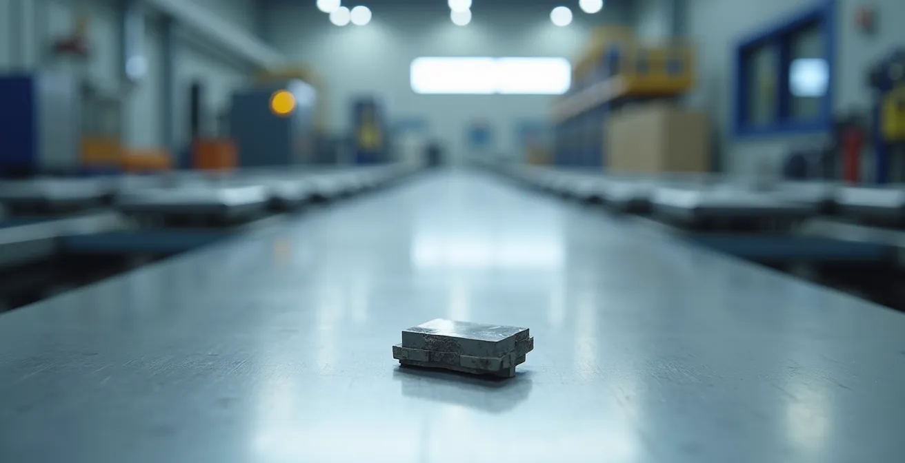
As the image of a worn tool shows, wear is inevitable. However, the *rate* and *mode* of wear are what matter. A good tool material will exhibit predictable, gradual wear rather than catastrophic failure like chipping or fracture. Polycrystalline cubic boron nitride (PCBN) and specific grades of tungsten-rhenium are often the go-to choices for aluminium, offering an excellent balance of wear resistance and toughness to achieve the desired long-term performance.
| Tool Material | Temperature Resistance | Wear Resistance | Application |
|---|---|---|---|
| Silicon Nitride Ceramics | Significantly higher than tungsten alloys | Excellent, extended tool life | High-temp alloys, steel, titanium |
| PCBN | Very High | Superior | Aluminum, copper alloys |
| Tungsten-Rhenium | High | Good | General aluminum applications |
Why replacing steel with carbon fibre isn’t just about weight, but stiffness?
The conversation around advanced materials in automotive design often centers on lightweighting. While reducing mass is a primary driver for improving EV range, the shift from traditional materials like steel to composites and advanced alloys is equally driven by the need for increased structural stiffness. This is especially true for the battery pack, which has evolved from a simple container to a critical, load-bearing component of the vehicle’s chassis in modern “skateboard” platform designs.
A stiff battery enclosure does more than just protect the cells; it contributes significantly to the overall torsional rigidity of the vehicle. This enhances handling, ride comfort, and, most importantly, crash performance. A rigid chassis deforms in a more predictable way during an impact, allowing safety systems to function as designed. Carbon fibre composites offer an exceptional stiffness-to-weight ratio, but pure composite designs can be complex and expensive to manufacture. Therefore, the dominant trend is a multi-material approach, combining extruded and cast aluminium sections with composite panels.
This is where FSW becomes an indispensable enabling technology. It provides the robust, high-strength method needed to join the various aluminium components of the tray’s frame, creating a rigid skeleton into which the composite elements are integrated. As the automotive industry’s reliance on aluminium grows, so does the need for superior joining methods.
The weight of aluminium used in cars is going to increase to 570 pounds by 2030.
– Industry forecast, High-speed friction stir welding study
This forecast underscores the urgency. As more structural functions are transferred to the aluminium battery tray, the quality of the welds becomes paramount. FSW ensures that the joints do not compromise the stiffness and strength that the designers intended to achieve through their material selection. It allows engineers to build a stiff, lightweight, and impact-resistant structure that serves as the backbone of the vehicle.
Solid-state vs MIG: which produces a ‘machined-look’ finish without grinding?
In a high-volume manufacturing environment, every process step adds time and cost. Post-weld finishing operations like grinding, spatter removal, and straightening are significant operational burdens associated with fusion welding processes like MIG (Metal Inert Gas). These steps are necessary to correct the surface defects and distortion inherent to melting and re-solidifying metal. FSW, by its very nature as a solid-state process, eliminates the root cause of these defects, delivering a superior surface finish directly off the tool.
Because FSW operates below the material’s melting point, it completely avoids issues like spatter, porosity, and oxidation that plague MIG welds. The process is more akin to forging than welding. The FSW tool plastically deforms and stirs the material, creating a joint with a fine, equiaxed grain structure. The surface of the weld, formed under the pressure of the tool’s shoulder, is smooth and clean, often described as having a “machined-look” appearance. This level of quality means that for many applications, including visible components, the FSW joint requires zero post-weld grinding or finishing.
This benefit has a direct and significant impact on the bottom line. It reduces cycle time, eliminates the labor and consumables associated with grinding, and creates a safer, cleaner workshop environment by removing a source of airborne particulates. The aesthetic quality is a valuable byproduct of a metallurgically superior process. The clean, consistent bead is a visual indicator of a high-integrity, defect-free joint, which is why it’s increasingly preferred for applications where both performance and appearance matter.
Key Takeaways
- Elimination of Thermal Damage: FSW’s solid-state nature prevents the warpage and material degradation (HAZ) common in fusion welding, ensuring the dimensional stability required for hermetic seals.
- Superior Joint Integrity: The process produces defect-free, high-strength joints with a fine-grained microstructure, achieving high joint efficiency that is critical for crash safety standards.
- Increased Production Efficiency: FSW combines competitive welding speeds with the elimination of post-weld grinding and finishing, leading to lower cycle times and reduced cost per part.
Smart Composites in Transport: Reducing Vehicle Weight by 20% to Boost EV Range
The relentless drive to reduce vehicle weight is the single most important factor in extending EV range and performance. While lightweight materials like smart composites and aluminium alloys are the building blocks, the manufacturing technologies that join them are the true enablers. Friction Stir Welding has firmly established itself not just as a joining method, but as a cornerstone of the advanced, automated manufacturing systems required to build the next generation of lightweight vehicles.
The concept of “smart composites” extends beyond the material itself to the entire manufacturing ecosystem. This includes intelligent process monitoring and quality control to ensure that every component meets its design specification with minimal human intervention. FSW is uniquely suited to this environment. Its process parameters—tool rotation speed, travel speed, and plunge force—can be precisely controlled and monitored in real time. This data provides a direct window into the quality of the weld as it is being formed.
Leading research and development efforts are now focused on integrating this data with artificial intelligence to create self-correcting welding systems. This represents the future of quality assurance in automotive manufacturing, moving from post-process inspection to in-process verification.
Future Outlook: AI-Powered Process Monitoring
In a forward-looking collaboration, KUKA is working with the University of Augsburg to develop an AI-based process monitoring system for FSW. The project aims to use sensor data collected during the welding process to monitor weld seam quality in real time. By identifying potential deviations or defects as they happen, the system can adjust parameters on the fly or flag a component immediately, drastically reducing downstream inspection time and costs. This integration of AI and FSW is a critical step towards fully autonomous, zero-defect production of lightweight vehicle structures.
For the automotive engineer, this means FSW is not a static technology but a platform for future innovation. By adopting FSW, you are investing in a process that is not only superior today but is also at the forefront of the industry’s move towards smart, data-driven manufacturing. It is the key to unlocking the full potential of lightweight materials and building safer, more efficient electric vehicles.
To integrate this superior joining technology into your next battery enclosure design, the logical next step is to evaluate its specific application to your materials and geometry. Begin by initiating a process feasibility study to define optimal parameters and validate joint performance for your unique requirements.
Frequently Asked Questions About Friction Stir Welding: Joining Aluminium and Copper for EV Battery Efficiency
Why does FSW produce superior surface finish?
FSW stirs and joins materials softened by frictional heat at a temperature below their melting point. This solid-state mechanism completely avoids fusion defects like spatter, undercutting, or oxidation, which are common in MIG or TIG welding and require secondary grinding operations.
How does grain structure affect surface appearance?
The intense plastic deformation during FSW creates a very fine-grained, forged microstructure in the joint. This is in stark contrast to fusion welds, which typically have a coarse, cast-like grain structure. The fine grains of an FSW joint contribute to its smooth, “machined-look” surface and superior mechanical properties.
What makes FSW suitable for visible automotive parts?
The combination of a smooth, forged surface texture and the absence of spatter or discoloration makes FSW ideal for components where aesthetics are important. The process delivers a clean, consistent, and high-quality finish directly from the tool, eliminating the need for costly and time-consuming post-weld cosmetic work.