Achieving true micron-level accuracy on complex aerospace parts has less to do with the CMM’s price tag and more with mastering the environmental and physical forces that actively corrupt data.
- Thermal expansion is not a minor nuisance; it’s a primary source of dynamic error that must be mathematically compensated for in real-time.
- Fixtures don’t just hold the part; they can induce micro-stresses that bend it into a non-conforming state during measurement.
Recommendation: Adopt a systemic approach: treat your entire measurement process—environment, fixture, probe, and machine—as an integrated system where every component is a potential variable.
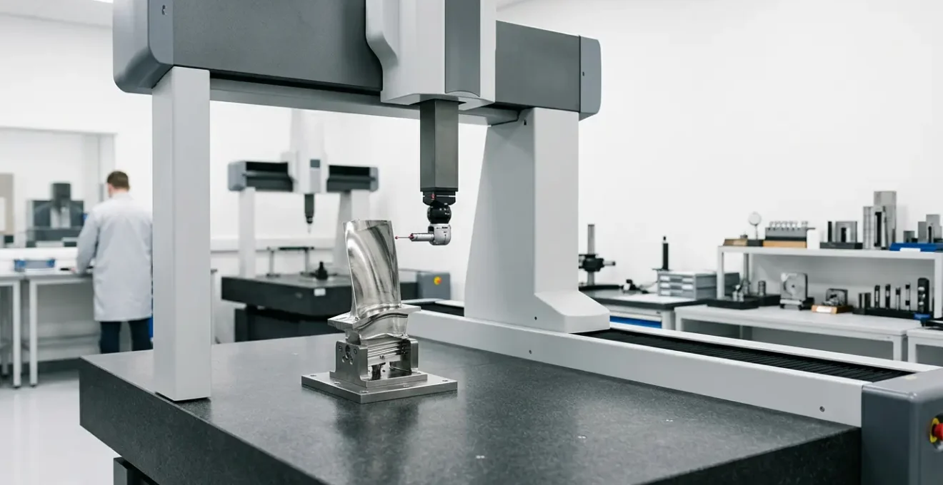
As a chief inspector in an aerospace machine shop, you’ve experienced the frustration. A critical component, a complex turbine blade or a structural bulkhead, measures perfectly within its tight tolerances on your state-of-the-art CMM. Yet, during assembly, it fails to fit. The immediate suspects are the usual: machine calibration, operator error, or a faulty probe. You run the checks, and everything seems perfect. The CMM is a fortress of precision, so where is the deviation coming from?
The common wisdom is to invest in better machines, more frequent calibrations, and stricter operator training. While essential, this focus on the visible aspects of metrology often misses the point. The most significant threats to micron-level accuracy aren’t always found on a calibration certificate. They are the invisible, dynamic forces actively working to corrupt your data from the moment a part is fixtured.
But what if the root cause of failure isn’t a static error but a dynamic one? What if the true enemy is the subtle change in temperature from morning to afternoon, the microscopic stress induced by the fixture itself, or the imperceptible deflection of the stylus as it traces a complex curve? The key to next-level precision isn’t just about measuring the part; it’s about mastering the physics of the measurement environment.
This guide moves beyond the spec sheet. We will dissect the unseen variables that sabotage complex geometry verification. We will explore how to identify, quantify, and compensate for these dynamic errors, transforming your quality control process from a simple check into a predictive science. You will learn to see your measurement lab not as a static room, but as a living system where every element matters.
To navigate these advanced concepts, this article is structured to deconstruct each major source of error. The following sections will guide you through the critical variables that define true micron-level accuracy, from environmental factors to tool selection strategy.
Summary: High-Precision Metrology for Complex Geometries
- Why your measurements fail at 2pm on a sunny day?
- How to qualify a stylus constellation for complex 5-axis parts?
- Tactile scanning vs Optical laser: which is more accurate for turbine blades?
- The fixturing error that bends the part during measurement
- How to interpret AS9102 First Article Inspection reports correctly?
- Why a fixed CMM cannot measure the interior of a large casting?
- How to calibrate CNC probes in-house to maintain micron-level tolerance?
- Inspection Tool Selection: CMM vs Portable Arms vs 3D Scanners
Why your measurements fail at 2pm on a sunny day?
The single greatest invisible enemy of micron-level precision is thermal expansion. A CMM room held at a stable 20°C (68°F) is standard practice, but this only addresses part of the problem. The part itself, the fixture, and even the CMM’s granite base retain thermal memory. A component machined in the morning and measured in the afternoon, when ambient sunlight has warmed one side of the facility, is not the same component. The material has physically changed size.
The scale of this issue in aerospace is not trivial. A component can experience a 140°F temperature differential between assembly and cruise conditions, illustrating the extreme thermal stresses these materials are designed for. While your shop floor won’t see such extremes, even a few degrees of deviation from the standard 20°C can push a tight tolerance part out of spec. This phenomenon, known as dynamic error, is a function of the material’s Coefficient of Thermal Expansion (CTE). Different materials expand and contract at different rates, meaning an aluminum part will react to temperature changes differently than a titanium fixture.
Relying solely on ambient room control is insufficient. The most advanced metrology departments treat thermal variation as a variable to be measured and compensated for mathematically. This involves a systematic thermal mapping protocol. By placing multiple thermal sensors on the part, the fixture, and the machine itself, you can create a 3D thermal gradient map. This data, combined with the known CTE of each material, allows the CMM software to apply real-time, vector-based compensation to every measurement point, effectively nullifying the effect of thermal drift. It’s about measuring the part as if it were at a perfect 20°C, regardless of its actual temperature.
How to qualify a stylus constellation for complex 5-axis parts?
Inspecting complex 5-axis parts, like blisks or impellers, requires a CMM probe that can reach deep into pockets and measure features at multiple angles. This is the domain of the stylus constellation—an intricate assembly of multiple styli of varying lengths and orientations. While these tools provide incredible access, they also introduce a significant risk: unmanaged probe deflection physics.
This macro shot provides a glimpse into the complexity of a modern stylus constellation, where each tip must be perfectly calibrated in a 3D space.
detail > artistic impact.”/>
Qualifying a single, straight stylus is straightforward. Qualifying a constellation is an exercise in 3D kinematics. Each tip has a unique vector and is subject to different leverage forces. A long, slender stylus will deflect more under contact pressure than a short, stout one. When a 5-axis head rotates to use a different stylus in the constellation, you are fundamentally changing the physics of the measurement. An uncalibrated or poorly qualified constellation doesn’t just produce an error; it produces an inconsistent, direction-dependent error that is maddeningly difficult to diagnose.
The qualification process must go beyond a simple touch on a reference sphere. It requires a comprehensive calibration routine that measures the sphere with every single stylus tip in the constellation, from multiple angles of approach. This process builds a precise 3D map of each tip’s position relative to the probe head’s pivot point. Modern CMM software uses this map to automatically compensate for the kinematic differences between styli. The goal is to ensure that a measurement taken with the long, angled stylus on the bottom of the part yields the exact same result as a measurement taken with the short, vertical stylus on the top.
Tactile scanning vs Optical laser: which is more accurate for turbine blades?
The choice of measurement technology for turbine blades and other freeform surfaces is a critical decision, as the quality inspection of engine components can account for 20% of total production cost and 25% of the production time. The debate often centers on tactile scanning versus non-contact optical lasers. The answer is not that one is “better,” but that they are optimized for different tasks. The key is understanding the difference between data-rich accuracy and feature-specific accuracy.
An optical laser scanner excels at capturing a dense point cloud of the entire airfoil surface in seconds. This is ideal for evaluating the overall profile, identifying surface defects, and performing comparative analysis against a CAD model. However, lasers can struggle with highly reflective surfaces and can have their accuracy compromised at the sharp, thin leading and trailing edges of a blade. Tactile scanning, while slower, provides superior accuracy for discrete, critical features. When you need to verify the precise radius of a leading edge or the exact location of a cooling hole to within a few microns, physical contact with a ruby-tipped probe is unparalleled.
The following table, based on common industry findings, breaks down the strengths of each method for specific turbine blade features. A best practice is often a hybrid approach: using an optical scanner for the overall form and a tactile probe for the flight-critical features on the same CMM cycle.
| Feature Type | Tactile Accuracy | Optical Accuracy | Recommended Method |
|---|---|---|---|
| Leading/Trailing Edge Radius | Superior (±2μm) | Moderate | Tactile |
| Overall Airfoil Profile | Good | Superior (high data density) | Optical |
| Cooling Hole Positions | Superior (±5μm) | Limited | Tactile |
| Surface Defects | Limited | Superior | Optical |
Case Study: Starrag Turbine Blade Measurement Optimization
Starrag, a leading manufacturer of aerospace components, demonstrated the immense productivity gains possible through technology optimization. By implementing a ZEISS PRISMO fortis CMM for turbine blade measurement, they were able to dramatically reduce inspection time. The standard measurement, which previously took 4 minutes and 30 seconds to produce accurate results, was reduced to just 70 seconds during the pilot phase, proving that the right combination of tactile and scanning technology can yield both speed and uncompromising accuracy.
The fixturing error that bends the part during measurement
A fixture’s job is to hold a part securely and repeatably. But in the world of micron-level metrology, the fixture can become another invisible enemy. The very act of clamping a component can introduce microscopic stresses that deform it. This fixture-induced stress can bend, twist, or bow a part, causing the CMM to measure a non-conforming shape that doesn’t actually exist when the part is in its free state. This is especially true for thin-walled or non-rigid aerospace components.
Imagine tightening a clamp on a thin aluminum housing. You might be applying force in one location, but that stress propagates through the material, potentially causing a section several inches away to bow upwards by a few microns. The CMM will faithfully report this deviation, leading to a false rejection. The error is not in the part or the machine; it is in the measurement process itself.
Mitigating this requires treating fixture design with the same rigor as part design. Standard clamps are often the culprit. Advanced fixturing techniques focus on holding the part without introducing stress. This includes using vacuum chucks for flat parts, which provide uniform holding pressure, or implementing kinematic nests that constrain the part at specific points without over-constraining it. For any clamped fixture, using torque-limited wrenches set to precise, material-specific specifications is non-negotiable. For ultimate precision, fixtures should be designed using Finite Element Analysis (FEA) to simulate clamping forces and identify potential part deformation before any metal is cut.
How to interpret AS9102 First Article Inspection reports correctly?
The AS9102 First Article Inspection (FAI) report is the ultimate birth certificate for an aerospace part. It’s more than a table of measurements; it is the definitive record that a component was produced in accordance with every specification on the drawing. However, its value is entirely dependent on the integrity of the data within it. Correctly interpreting an FAI report means looking beyond the “Pass/Fail” column and scrutinizing the chain of traceability for every single dimension.
A “ballooned” drawing, with callouts for every specified dimension, is the map for the FAI. But the report itself is the territory, and it must be flawless.
clarity > symbolism.”/>
A common failure point is Form 3, the “Characteristic Accountability, Verification and Compatibility Evaluation” sheet. This is where the story of each measurement is told. A number in a cell is meaningless without its context. Who measured it? With what instrument? When was that instrument last calibrated? What were the environmental conditions at the time of measurement? A robust FAI report links every measured value back to a specific, calibrated instrument serial number and a documented set of environmental conditions. Without this unbroken chain, the report is merely a list of numbers, not a verifiable document of conformance.
As a chief inspector, auditing an incoming FAI requires a forensic mindset. You are not just checking numbers; you are verifying a process. The checklist below outlines the critical traceability points to verify on any AS9102 Form 3.
Action Plan: Your AS9102 Form 3 Traceability Audit
- Verify all material certifications are present and match part number requirements.
- Check special process certifications (heat treatment, coating, NDT) and ensure their dates are valid.
- Confirm that calibration certificates are on file for all measurement instruments used in the report.
- Link each measured dimension on Form 3 to a specific, calibrated equipment serial number.
- Document the environmental conditions (temperature, humidity) during the measurement for critical dimensions.
Why a fixed CMM cannot measure the interior of a large casting?
A traditional bridge-style CMM is a paragon of accuracy, but it has a fundamental limitation: line of sight. The probe can only measure what it can physically touch. For large, complex components like engine casings or structural castings, this presents a significant challenge. How do you verify the wall thickness in the center of a hollow casting? How do you inspect for internal porosity or check the geometry of an internal channel created through additive manufacturing?
This is where the capabilities of fixed, tactile CMMs end. You cannot measure what you cannot reach. While long probes and articulated heads can extend the reach, they cannot see through solid material. This is a critical blind spot, especially with the rise of additively manufactured parts, which introduce new questions about internal porosity, layerwise geometry, and residual stress hidden within the component’s structure.
The solution lies in moving beyond touch and into technologies that can see inside a part. Industrial Computed Tomography (CT) scanning is the ultimate tool for this task. Much like a medical CT scan, an industrial scanner uses X-rays to create a complete, three-dimensional model of a part, both inside and out. This allows for a complete “digital twin” of the component, from which you can extract any dimension, analyze wall thickness, and, crucially, identify internal defects like voids or porosity that would be completely invisible to a CMM. For complex internal geometries, CT scanning is not just an alternative; it is the only viable method for complete verification.
How to calibrate CNC probes in-house to maintain micron-level tolerance?
A CMM’s stated accuracy is a theoretical maximum. In practice, the system is in a constant state of what can be called measurement entropy—a natural tendency to drift away from its perfectly calibrated state due to thermal changes, vibration, and simple wear and tear. A machine that achieves a 0.9 + L/350 µm length measurement error does so only when this entropy is actively and constantly fought through rigorous calibration. Relying solely on an annual service contract is not enough for high-stakes aerospace work.
Maintaining micron-level tolerance requires an in-house, high-frequency calibration protocol centered around a master artifact. This isn’t just about running the machine’s built-in calibration cycle. It’s about a systematic process designed to catch and correct drift before it impacts production parts. This involves creating a dedicated master artifact with features (spheres, bores, planes) that closely mimic the parts you regularly measure. This makes the calibration directly relevant to your specific production.
The protocol must be comprehensive. It should perform both length and diameter calibrations separately to prevent the software from averaging out and masking tapering errors in the probe tip. For ultimate stability, this automated calibration cycle should be run frequently—every few hours in some shops—to compensate for the machine’s thermal drift as it warms up and cools down throughout the day. This discipline, combined with regular verification of the probe stylus condition under magnification and quarterly checks against a certified reference standard, is what separates a good metrology lab from a world-class one. It’s about owning the accuracy of your process every single hour of every day.
Key takeaways
- True precision is systemic; it requires managing the interplay between the machine, the environment, the fixture, and the part itself.
- Dynamic errors, especially thermal expansion, are a primary source of measurement failure and must be actively compensated for, not just passively controlled.
- The right tool is feature-dependent; hybrid approaches combining the speed of optical scanning with the precision of tactile probing often yield the best results.
Inspection Tool Selection: CMM vs Portable Arms vs 3D Scanners
The final piece of the metrology puzzle is selecting the right instrument for the task at hand. There is no single “best” tool. A fixed bridge CMM, a portable measurement arm, and a 3D laser scanner are all essential components of a modern aerospace quality department, each with a distinct role. The strategic error is using a high-accuracy tool for a low-accuracy job (wasting time and resources) or, more dangerously, using a low-accuracy tool for a flight-critical measurement.
The selection should be driven by a clear matrix of accuracy requirements, part size, and feature complexity. A fixed bridge CMM offers the highest level of accuracy (±2-5μm) and is the undisputed choice for flight-critical components like engine disks or landing gear components. Portable arms offer greater flexibility for large assemblies, like inspecting a fuselage section on the shop floor, but at a lower accuracy (±25μm). For even larger volumes, laser trackers can achieve an up to 50m measurement range. 3D scanners, meanwhile, are the fastest solution for capturing the overall shape of less critical parts like brackets or interior panels, where speed is more important than micron-level precision.
The following matrix provides a clear framework for this strategic decision-making process, aligning the right technology with the right application to optimize both quality and efficiency.
| Tool Type | Best For | Accuracy | Speed | Cost |
|---|---|---|---|---|
| Bridge CMM | Flight-critical parts | ±2-5μm | Slow | High |
| Portable Arms | Large assemblies | ±25μm | Medium | Medium |
| 3D Scanners | Non-critical brackets | ±50μm | Fast | Low |
| On-Machine Verification | Production parts | ±10μm | Very Fast | Low |
By understanding and mastering these invisible forces and making strategic tool choices, you move beyond simply operating a CMM. You begin to conduct the entire orchestra of metrology. Begin today by implementing this systemic approach to measurement, transforming your quality control from a simple gatekeeper into a predictive, strategic asset that drives manufacturing excellence.