The right choice isn’t picking one tool, but building a hybrid metrology strategy that assigns the best technology to each specific stage of your workflow.
- Fixed CMMs provide micron-level accuracy for critical features but create inspection bottlenecks.
- Portable arms and scanners bring measurement to the part, drastically reducing downtime and enabling 100% inspection.
Recommendation: Audit your current inspection bottlenecks to identify where portable and scanning technologies can complement, not just replace, your existing CMM capabilities.
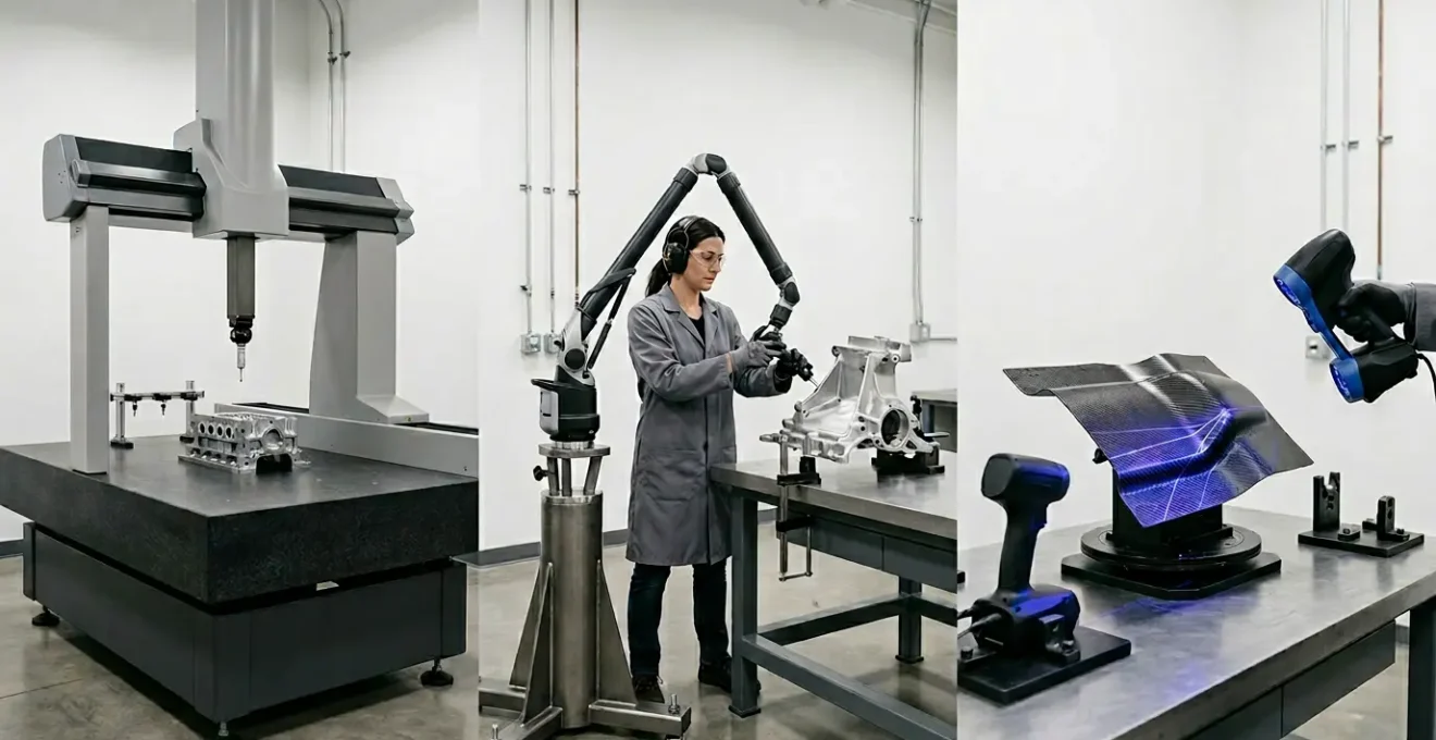
As a quality manager, you face a recurring and critical decision: a new project lands, featuring complex geometries and tight tolerances, and you must select the right inspection technology. The market presents a confusing array of options, primarily centered around three core technologies: the traditional Coordinate Measuring Machine (CMM), the flexible portable measuring arm, and the high-speed 3D laser scanner. You’ve likely heard the standard arguments—CMMs are the gold standard for accuracy, portable arms offer versatility, and 3D scanners are unmatched for capturing vast amounts of surface data quickly. While true, these are platitudes that oversimplify the choice.
Framing this as a “one-or-the-other” battle is a strategic error that can lock your quality department into inefficiency. The most advanced manufacturing operations don’t just buy a tool; they design an integrated measurement strategy. This approach moves beyond a simple comparison of specifications to answer a more fundamental question: which technology is the right tool for the specific measurement task at the right stage of the production process? The goal isn’t to find the single “best” tool, but to orchestrate the “right mix” of tools to eliminate bottlenecks, improve data integrity, and accelerate feedback to the production floor.
This guide is designed to help you build that strategy. We will move past generic pros and cons to analyze specific, high-stakes scenarios that quality managers face daily. By understanding the underlying principles of why one tool excels where another fails, you can make an informed, defensible investment that enhances your entire quality ecosystem, from initial prototyping to final assembly verification.
This article will deconstruct the decision-making process by exploring real-world manufacturing challenges. We’ll examine the specific limitations and strengths of each technology in context, providing a clear framework for building a versatile and efficient metrology toolkit.
Summary: A Manager’s Guide to Building a Modern Metrology Strategy
- Why a fixed CMM cannot measure the interior of a large casting?
- How to calculate the time saved by measuring parts on the machine?
- Blue light vs Laser line: which handles shiny surfaces better?
- The operator handling mistake that ruins micrometer accuracy
- How to qualify a stylus constellation for complex 5-axis parts?
- Laser interferometry vs Mechanical gauges: which is needed for aerospace parts?
- High-Precision Metrology: Verifying Complex Aerospace Geometries Down to the Micron
- When to retire analogue gauges for digital data collection tools?
Why a fixed CMM cannot measure the interior of a large casting?
The primary limitation of a fixed CMM, despite its unparalleled accuracy, is its reliance on a direct line-of-sight probing system within a confined measurement volume. For a large, heavy casting, two problems immediately arise. First, the part may be too large or unwieldy to fit on the CMM’s granite table. Second, even if it fits, the CMM’s probe cannot physically reach deep internal cavities, undercuts, or features obscured by other sections of the casting. The probe requires a clear path to touch a surface, which is often impossible for complex internal geometries. While CMMs are the authority for precision, with accuracies reaching 1-2 microns compared to 40-50 for many scanners, this strength is irrelevant if the feature cannot be reached.
This is where a hybrid metrology strategy becomes essential. Instead of viewing it as a failure of the CMM, a strategic approach uses the CMM for what it does best and complements it with portable technology. The CMM can be used to establish a highly accurate primary datum reference frame on the accessible exterior of the casting. Then, a portable 3D scanner or a probed arm is used to capture the hard-to-reach internal features. The data from the portable system is then aligned to the CMM’s high-precision reference frame within the metrology software, creating a single, complete, and highly accurate data model.
Case Study: Hybrid Metrology for Large Casting Inspection
A prime example of this strategy in action involves combining different portable tools. A Creaform case study highlights a hybrid approach using the MetraSCAN 3D scanner and a HandyPROBE. For a large part, the CMM or a portable probing system establishes the critical external datum framework with maximum precision. Subsequently, the optical 3D scanner captures the freeform surfaces and internal geometries. This combined method successfully achieves an accuracy of 0.020mm even in variable shop floor conditions, demonstrating that blending technologies delivers a result that no single tool could achieve alone.
This approach transforms the problem from “which tool is better?” to “how can my tools work together?”. It leverages the CMM for its core strength in establishing foundational accuracy while using the flexibility of portable scanners to overcome its physical limitations.
How to calculate the time saved by measuring parts on the machine?
The most significant hidden cost of relying solely on a fixed CMM is the creation of an operational bottleneck. The traditional workflow involves removing a part from the machine tool, transporting it to the climate-controlled CMM room, waiting in a queue for inspection, performing the measurement, and finally returning the results to the shop floor. This entire process can take hours, during which the machine tool sits idle or, worse, continues producing potentially non-conforming parts. On-machine measurement with a portable arm or scanner fundamentally breaks this bottleneck.
By bringing the measurement device directly to the part while it is still on the machine tool, inspection time is reduced from hours to minutes. This provides immediate feedback for tool offset adjustments, significantly reducing scrap and rework. The impact is substantial; industry analysis reveals up to a 50% reduction in overall inspection times with the integration of such Industry 4.0 metrology practices. Calculating the return on investment (ROI) for a portable system becomes a straightforward exercise in quantifying the value of this reclaimed time.
This visualization starkly contrasts the idle downtime of traditional CMM workflows with the productive, in-process nature of on-machine measurement, highlighting the direct impact on production throughput.
To justify the investment to management, you must translate “time saved” into a concrete financial figure. This involves calculating the total cost of machine downtime and comparing it to the efficiency gains of an on-machine inspection workflow. The following checklist provides a framework for this calculation.
Action Plan: Calculating the Total Cost of CMM Downtime
- Calculate Machine Hourly Rate: Sum the total cost of running your CNC machine per hour, including equipment depreciation, operator wages, and factory overhead.
- Measure Traditional CMM Transfer Time: Clock the entire process: part removal, transport to the lab, queuing time, CMM measurement cycle, and transport back. This is your “downtime per inspection.”
- Compare with On-Machine Duration: Measure the time required to inspect the same critical features using a portable arm or scanner directly on the machine tool (typically 5-15 minutes).
- Quantify Throughput Gain: Multiply the time saved per part by the number of production batches per shift. This represents the additional production capacity unlocked.
- Factor in Scrap Prevention: Estimate the cost of scrap parts produced during the delay before CMM feedback is received (e.g., 4 hours of production). On-machine inspection provides near-instant feedback, preventing this waste.
By following these steps, you can present a clear business case demonstrating that a portable measurement system is not a cost center, but a driver of profitability through increased uptime and reduced waste.
Blue light vs Laser line: which handles shiny surfaces better?
When selecting a 3D scanner, one of the most critical technical considerations is the light source, typically a red laser or a blue laser/LED. This choice directly impacts the scanner’s ability to handle different material surfaces, especially reflective or dark ones. The core issue with shiny surfaces is light scattering. A scanner works by projecting a pattern onto a part and a camera capturing its deformation. On a shiny surface, a longer wavelength light source, like a red laser, tends to scatter widely, creating “noise” in the data and making it difficult for the camera to get a clean reading. This often forces operators to apply a temporary matte spray to the part, adding an extra, time-consuming step.
Blue light technology offers a distinct advantage here. As a technology provider, Kreon Technologies, explains, blue light is a superior solution for these challenging surfaces.
Blue laser 3D scanners optimize the scanning of parts regardless of their dimensions, appearance, or material, with the resulting mesh being dense and accurate, perfectly reflecting the real part.
– Kreon Technologies, Kreon 3D Measurement Systems Technical Documentation
The reason lies in physics. Blue light has a shorter wavelength (around 450-490nm) compared to a red laser (630-680nm). This shorter wavelength is less susceptible to scattering on metallic and glossy surfaces. It projects more sharply, allowing the camera to capture a cleaner, higher-resolution point cloud with significantly less noise, often eliminating the need for any surface preparation. While red laser line scanners can be faster over large, matte surfaces, blue light is the clear winner for applications involving polished, machined, or dark-colored parts where data quality is paramount.
This table summarizes the key performance differences between the two technologies, providing a clear basis for selection based on your typical applications and materials.
| Feature | Blue Light Scanner | Red Laser Line |
|---|---|---|
| Wavelength | 450-490nm (shorter) | 630-680nm (longer) |
| Surface Scattering | Minimal on shiny surfaces | High scatter requiring spray |
| Spray Requirement | None | Often required |
| Scan Speed | Moderate | Fast on large areas |
| Deep Feature Capture | Good | Excellent |
| Data Noise Level | Low | Higher on reflective |
Therefore, if your workflow frequently involves inspecting machined metal components, polished molds, or carbon fiber parts, investing in a blue light scanner will save significant time and produce more reliable data from the outset.
The operator handling mistake that ruins micrometer accuracy
The classic mistake with a hand tool like a micrometer is inconsistent torque, leading to over-tightening. However, as quality departments transition to more advanced portable tools like 6-axis CMM arms, the sources of operator-induced error evolve but do not disappear. The fundamental mistake remains the same: inconsistent physical handling. With a portable arm, this manifests as inconsistent probing pressure, slight drifts during measurement, or unstable machine positioning. These subtle variations can easily negate the instrument’s inherent precision.
Portable arms are highly capable instruments, but their accuracy is a symbiotic relationship between the machine and the operator. According to an analysis by CMMXYZ, 6-axis arms can achieve accuracies between 15-20 µm with a solid probe, but this is highly dependent on operator experience. The report emphasizes that maintaining consistent probing pressure is critical for achieving repeatable results. An operator who probes a point with slightly more force than the next can introduce several microns of error, a significant deviation when working with tight tolerances. The stability of the arm’s mounting and the operator’s ability to hold the probe steady during data capture are equally vital.
To mitigate these human factors, modern metrology systems incorporate “Poka-Yoke” (mistake-proofing) principles directly into the hardware and software. These features are designed to guide the operator and prevent common errors before they occur. Implementing these solutions is key to ensuring that the accuracy you paid for is the accuracy you get in practice. Key strategies include:
- Guided Measurement Sequences: Software with visual prompts that walk the operator through a pre-defined inspection plan, ensuring no features are missed and the sequence is correct.
- Real-time Stability Feedback: On-screen indicators that alert the operator if the arm or probe is drifting or vibrating during a measurement.
- Automated Force and Angle Detection: Systems that can detect excessive probing force or automatically compensate for the probe’s angle, like ZEISS’s articulating probe heads which offer 5,184 different angles for better ergonomics.
- Mandatory Re-calibration Prompts: Software that enforces periodic checks against a calibration sphere to account for any drift caused by temperature changes or minor impacts.
Relying solely on operator skill is a fragile strategy. Building a robust quality process means implementing systems that make it easy for operators to do the right thing and hard to do the wrong thing.
How to qualify a stylus constellation for complex 5-axis parts?
Inspecting complex 5-axis machined parts, such as aerospace components or intricate molds, often requires a CMM probe with a “star” or “constellation” stylus configuration. This setup, with multiple styli pointing in different directions, allows the probe to measure various features and undercuts in a single setup, avoiding time-consuming tool changes. However, the accuracy of the entire inspection hinges on the precise qualification of this complex arrangement. Qualification is the process of telling the CMM software the exact position and diameter of each stylus tip relative to the others. A poor qualification will render all subsequent measurements invalid.
The method you choose for qualification is a trade-off between speed, accuracy, and the complexity of your probe setup. For simple, single-stylus probes, the traditional single-sphere method is sufficient. But for a star probe, this method becomes tedious and prone to error. Advanced techniques are required to ensure the entire constellation is qualified as a single, rigid entity. To aid in this, leading manufacturers now invest up to 10% of their R&D budgets in metrology simulation tools, which can predict collisions and optimize qualification paths before ever touching the machine.
This macro photograph reveals the intricate geometry of a multi-stylus star probe as it makes contact with a precision calibration sphere, a critical step in ensuring measurement accuracy for complex parts.
The selection of a qualification method should be a deliberate choice based on your specific requirements for accuracy and compliance, as different methods yield vastly different results in terms of time and precision.
| Qualification Method | Time Required | Accuracy | Best For |
|---|---|---|---|
| Virtual CMM Simulation | 30 min setup | Predictive only | Pre-collision detection |
| Single Sphere Method | 15 min/stylus | ±2 µm | Simple configurations |
| Multi-Sphere Array | 45 min total | ±1 µm | Star/T-probes |
| ISO 10360 Protocol | 60-90 min | Certified ±0.5 µm | Audit compliance |
For high-value, complex parts, relying on the single sphere method for a star probe is a false economy. The time saved is not worth the risk of questionable data. Using a multi-sphere array or a certified protocol like ISO 10360 is the only way to guarantee the integrity of your measurements and ensure full traceability.
Laser interferometry vs Mechanical gauges: which is needed for aerospace parts?
In aerospace manufacturing, measurement challenges are defined by two extremes: immense scale and microscopic tolerances. When aligning large structural components like a wing to a fuselage or verifying the geometry of a tooling jig that spans dozens of feet, traditional mechanical gauges (like feeler gauges, calipers, or even large fixtures) become wholly inadequate. They are cumbersome, prone to operator error, and, most importantly, susceptible to environmental instability. A slight change in temperature over the length of a 20-foot mechanical gauge can introduce significant measurement error.
This is where laser-based systems, such as laser trackers and laser interferometers, become not just a preference, but a necessity. These instruments use a laser beam as the measurement standard, providing extraordinary accuracy over vast distances. As noted in a ZEISS Metrology guide, “Portable laser CMMs give accurate measurement over long distances — up to 220-240 feet, making these portable CMMs a common choice for large part manufacturing and assembly.” This capability is fundamentally impossible for a physical, mechanical tool to replicate.
The true advantage of high-end laser systems for aerospace, however, goes beyond just distance. It lies in their ability to perform active environmental compensation. A laser tracker system doesn’t just project a beam; it simultaneously monitors air temperature, pressure, and humidity along the beam’s path in real-time. According to an aerospace application note by Exact Metrology, this active compensation is crucial for maintaining micron-level accuracy during critical operations like wing-to-fuselage alignment. The system’s software continuously recalculates the laser’s wavelength based on the atmospheric conditions, correcting for variations that would otherwise introduce significant errors. A mechanical gauge has no such capability; its physical length changes with temperature, and this change goes uncorrected.
For any large-scale application where precision is non-negotiable, the debate is effectively over. Laser interferometry and tracking systems are the required standard, providing the unique combination of long-range capability, high precision, and environmental stability that aerospace manufacturing demands.
High-Precision Metrology: Verifying Complex Aerospace Geometries Down to the Micron
Verifying the complex, freeform geometries of aerospace components like turbine blades, nacelles, or airfoils presents a challenge that pushes traditional measurement methods to their limits. These parts are defined not by simple prismatic shapes but by thousands of individual surface points that must conform to a precise aerodynamic profile. Using a touch-probe CMM for this task is extraordinarily slow and provides an incomplete picture. The CMM might sample 300 points across a turbine blade, but it completely misses the surface condition between those points.
This is the domain where 3D scanning provides a revolutionary advantage. Instead of discrete points, a scanner captures a dense “point cloud” of the entire surface. The difference in data richness is staggering; comparative analysis shows that 3D scanners can capture millions of points in the time it takes a touch probe to capture a few hundred. This high-density data allows for a far more comprehensive analysis of the part’s overall form, enabling the detection of subtle deviations, surface waviness, or blending errors that a touch-probe would miss entirely. By comparing this dense “as-built” point cloud to the original CAD model, engineers can generate detailed color maps that instantly visualize any deviation across the entire part surface.
The ultimate application of this high-density data is the creation of a digital twin. This is not just a 3D model; it is a highly accurate, data-rich virtual replica of the physical part, integrating both high-density scan data and high-precision CMM data. This digital twin becomes a foundational asset for the part’s entire lifecycle.
The workflow for creating a robust digital twin for an aerospace component is a multi-stage process that leverages the strengths of multiple metrology tools:
- High-Density Data Capture: Use a high-resolution blue light scanner to capture a dense point cloud of all freeform surfaces, often at a rate of over 1 million points per second.
- Critical Feature Probing: Use a CMM or a probed portable arm to measure critical datum features (bores, planes, bolt patterns) to the highest possible accuracy.
- Dataset Merging: Integrate the high-density scan data and the discrete probe data in a unified metrology software platform, aligning them to a common coordinate system.
- GD&T and Form Analysis: Generate a comprehensive inspection report, including a color map of surface deviation and a full GD&T analysis of the probed features.
- Lifecycle Integration: Export the as-built digital twin to CAE software for further analysis, such as wear prediction, stress simulation, or reverse engineering.
This process, outlined by industry leaders like Artec 3D in their metrology guides, represents the pinnacle of modern quality control, providing a level of insight and traceability that was previously unattainable.
Key Takeaways
- A hybrid metrology strategy, combining fixed CMMs with portable systems, is more effective than relying on a single tool.
- On-machine measurement with portable arms or scanners eliminates CMM bottlenecks, providing a clear and calculable return on investment.
- The right technology (e.g., blue light vs. laser) must be chosen based on your specific materials and features, not just general specifications.
When to retire analogue gauges for digital data collection tools?
The decision to retire trusted analogue gauges like calipers, micrometers, and height gauges in favor of digital tools is often met with resistance. They are simple, reliable, and require no software. However, in a modern manufacturing environment focused on traceability and data-driven process control, they have a critical flaw: they create “data islands.” A measurement taken with a caliper typically ends its life scribbled on a piece of paper, with no direct link to the part, the operator, or the machine. This manual data entry is slow, prone to transcription errors, and makes statistical process control (SPC) nearly impossible.
The transition to digital hand tools and integrated data collection systems is not just about convenience; it is a strategic move to improve data integrity and efficiency. The financial incentive is significant, as market analysis confirms an average 20% cost reduction can be achieved through the implementation of automated quality control processes that rely on digital data streams. The question is not *if* you should transition, but *when*. The decision should be based on a clear-eyed assessment of your operational needs, traceability requirements, and production volume.
To move this from a subjective feeling to an objective decision, you can use a scorecard framework. By assigning points to key criteria, you can determine if you are at a “tipping point” where the costs and risks of staying with analogue tools outweigh the benefits. The following scorecard, adapted from market analysis by firms like Grand View Research, provides a structured way to evaluate your situation.
| Assessment Criteria | Stay Analog (0-2 pts) | Consider Digital (3-4 pts) | Go Digital Now (5+ pts) |
|---|---|---|---|
| Annual Volume | <1000 parts | 1000-5000 parts | >5000 parts |
| Traceability Requirements | Basic records | ISO compliance | AS9102/FDA regulated |
| Operator Count | 1-2 skilled | 3-5 operators | >5 or high turnover |
| SPC Implementation | Not required | Manual charts | Real-time monitoring |
| Integration Needs | Standalone | Some ERP links | Full QMS integration |
If your total score is in the 5+ range, continuing with analogue gauges is actively hindering your quality department’s performance. The risk of data-entry errors, the cost of manual reporting, and the inability to perform real-time SPC create a compelling business case for investing in a digital data collection system.
Use this strategic framework to audit your current processes, build a compelling business case for your next metrology investment, and transform your quality department into a proactive, data-driven asset for your entire organization.