
Adding electric fleet charging is not a simple add-on; it is a full-scale stress test of your entire site’s utility infrastructure, where the true bottlenecks are often hidden in plain sight.
- Your main incomer fuse, not just grid capacity, is the most immediate barrier to electrification and expansion.
- On-site energy storage (BESS) offers not only resilience but also revenue streams that diesel generators cannot match.
Recommendation: Shift from thinking about ‘adding chargers’ to conducting a holistic site infrastructure audit—from electrical incomers and water pipework to the load-bearing capacity of your floors.
As a Site Services Manager, you’re on the front line of the next great industrial shift: fleet electrification. The directive has come down to transition your commercial vehicles to electric, and the pressure is on. The common approach is to start getting quotes for EV chargers, perhaps considering a few solar panels. But this view is dangerously narrow. The real challenge isn’t about bolting a few chargers to a wall; it’s about whether your site’s entire utility backbone, often decades old, can withstand the colossal new demand.
The introduction of a significant EV charging load is the equivalent of adding an entirely new production line, operating at full tilt. This new demand doesn’t just stress your electrical system; it exposes weaknesses across your entire infrastructure. Suddenly, the capacity of your main incomer fuse, the integrity of your compressed air pipework, and even the structural strength of your concrete floors become critical points of failure. The conversation must shift from “Which charger should we buy?” to “Is our fundamental infrastructure fit for a Megawatt-scale future?”
This isn’t about simply meeting a sustainability target. It’s about future-proofing your production capabilities. Relying on superficial solutions like basic smart charging without a deep infrastructure audit is a recipe for crippling operational disruptions, unforeseen capital expenditure, and missed opportunities. This guide moves beyond the platitudes. We will dissect your site as an interconnected system, revealing the hidden bottlenecks and strategic opportunities to build a resilient, high-performance manufacturing environment ready for the electric age.
This article provides an infrastructure consultant’s perspective on preparing your site for the future. We will explore the critical systems, from the main electrical incomer to on-site renewable generation, providing a clear roadmap for your site’s evolution.
Summary: A Holistic Guide to Site Infrastructure for Electrification
- Why your main incomer fuse is the biggest bottleneck to expansion
- How to redesign pipework to stop pressure drops killing tool performance
- Diesel generators vs Battery Storage (BESS): which is better for grid resilience?
- The hidden leak costs that bloat your trade effluent bill by £5k/year
- When to start infrastructure planning for hydrogen-fuelled furnaces?
- Why relying solely on the National Grid exposes you to peak-hour surcharges
- How to strengthen floors to support heavier modern machinery
- Solar or Wind? Choosing the Right Renewable System for UK Manufacturing Sites
Why your main incomer fuse is the biggest bottleneck to expansion
Before you even think about the National Grid’s capacity, the single greatest chokepoint in your electrification journey is likely the main fuse at your site’s incomer. This single component dictates the absolute maximum power, measured in kilovolt-amperes (kVA), that your entire facility can draw. Adding a bank of fast chargers for an electric fleet can easily represent a 25-30% increase in your site’s peak load, pushing you far beyond the rating of your existing fuse and supply cable. An undersized incomer will lead to nuisance tripping, production downtime, and ultimately, a hard limit on your ability to expand operations or install new machinery.
The process of upgrading this connection is not trivial. It involves extensive consultation with the Distribution Network Operator (DNO), the company that manages the local power grid. However, relying solely on their desktop records can be misleading and costly. Physical verification is paramount.
Case Study: The Importance of Physical Verification
While a residential example, the principle is directly applicable at an industrial scale. A UK homeowner seeking a main fuse upgrade for a new EV charger was quoted £7,000 by their DNO, Western Power. The quote was based on records indicating an undersized 16mm² supply cable. However, a physical site inspection requested by the owner revealed that a larger, fully capable cable and a 100A fuse were already installed. The DNO’s records were outdated, and the upgrade was unnecessary. This highlights a critical lesson for site managers: never trust DNO records without a physical survey of your own infrastructure. The cost of a few hours for an electrical contractor to inspect your incomer is negligible compared to the potential cost of an unnecessary and disruptive substation upgrade.
Assessing your true capacity requires a methodical approach before engaging the DNO. You need to establish a data-backed case for what you currently use versus what you will need. This baseline data is your most powerful tool in any negotiation or planning discussion.
Action Plan: Assessing Your Incomer Capacity Needs
- Physical Cable & Tail Inspection: Verify the cross-sectional area of your incoming supply cable and meter tails. For a typical 100A industrial supply, a 25mm² cable is the minimum standard.
- Peak Load Monitoring: Install a peak current monitor (like a data logger) on your main supply for a typical production week. This will reveal your actual peak demand, which is often very different from your theoretical maximum.
- Future Load Calculation: Accurately calculate the additional load from the proposed EV fleet and any other planned machinery acquisitions in the next 3-5 years.
- DNO Consultation: Armed with your physical inspection data and load monitoring results, formally consult the DNO about the capacity of the local low-voltage (LV) network and the feasibility of an upgrade.
- Explore Load Management: If a physical upgrade is prohibitively expensive or has a long lead time, investigate dynamic load management systems that can intelligently balance the EV charging load against other site demands to stay under your fuse limit.
How to redesign pipework to stop pressure drops killing tool performance
While electrical capacity is the headline issue, the performance of your plant is equally dependent on other utilities like compressed air and water. An infrastructure audit that ignores your pipework is incomplete. As you add new production lines or reconfigure layouts, you may inadvertently create significant pressure drops in your compressed air system. These drops starve pneumatic tools and automated machinery of the required pressure (measured in bar or psi), leading to reduced cycle times, quality control failures, and premature equipment wear. The problem is rarely the compressor itself, but the journey the air takes to the tool.
The primary culprits are often an undersized main pipe diameter, an excessive number of sharp 90-degree bends, and long, convoluted pipe runs. Every bend, valve, and fitting adds to the cumulative friction loss, bleeding pressure from the system. A system that was adequate a decade ago can quickly become a performance bottleneck when asked to supply more tools or equipment further from the compressor room. Redesigning for efficiency means thinking in terms of fluid dynamics: creating the path of least resistance for your compressed air.
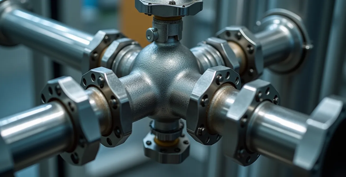
The solution lies in a ‘ring main’ or ‘closed-loop’ pipework design. Instead of a single, long ‘branch’ system where pressure diminishes at the furthest point, a ring main creates a continuous loop around the production area. This allows air to reach a tool from two directions, dramatically reducing the distance it travels and stabilising pressure across the entire facility. Upgrading key sections of the loop to a larger diameter pipe can further increase the system’s overall capacity, acting as a reservoir of ready-to-use compressed air.
Furthermore, installing pressure sensors at critical points in the network provides invaluable data. By monitoring pressure differentials, you can pinpoint exactly where the largest drops are occurring and target your upgrade efforts for maximum return on investment. This data-driven approach transforms pipework maintenance from a reactive guesswork exercise into a proactive performance optimisation strategy.
Diesel generators vs Battery Storage (BESS): which is better for grid resilience?
Grid resilience is a non-negotiable for any modern manufacturing site. Production stoppages due to power outages can cost tens of thousands of pounds per hour. For decades, the default solution has been the diesel generator. It’s a known quantity, capable of providing long-duration power during extended blackouts. However, in the context of a modern, electrified site, the diesel generator’s slow response time, high operating costs, and environmental impact make it a legacy solution. The strategic alternative is a Battery Energy Storage System (BESS).
A BESS offers near-instantaneous power, switching over in milliseconds compared to the 10-20 seconds a generator needs to start and synchronise. This speed protects sensitive electronic equipment and CNC machinery from the data loss and damage caused by even a momentary power interruption. More importantly, a BESS transforms your site from a passive energy consumer into an active grid participant. Unlike a diesel generator that sits idle 99% of the time, a BESS is a working asset. It can be programmed to charge during off-peak hours when electricity is cheap and discharge during expensive peak periods—a strategy known as ‘peak shaving’.
This capability to manage your load has a direct and significant impact on your bottom line. As noted by one analysis, “shifting 80% of energy consumption to overnight rates can cut electricity costs by 30-40%”. This is precisely what a BESS enables. Furthermore, you can participate in grid-balancing services, selling stored energy back to the DNO during periods of high demand to generate additional revenue streams. This transforms a cost centre (energy resilience) into a profit centre.
The choice between diesel and BESS depends on your specific risk profile. A diesel generator still holds an advantage for providing power during multi-day blackouts, but for the far more common short-term outages and for daily cost optimisation, a BESS is strategically and financially superior.
To make an informed decision, a direct comparison is essential. This table outlines the key differences between the two technologies for an industrial setting.
| Aspect | Diesel Generators | Battery Storage (BESS) |
|---|---|---|
| Response Time | 10-20 seconds startup | Less than 20ms switchover |
| Revenue Generation | Backup only | Grid services, frequency response, capacity markets |
| Operating Costs | Fuel volatility, regular maintenance | Minimal maintenance, no fuel costs |
| Environmental Impact | Emissions, noise pollution | Zero emissions, silent operation |
| Best Use Case | Prolonged multi-day blackouts | Short-term outages, peak shaving, daily cycling |
The hidden leak costs that bloat your trade effluent bill by £5k/year
Your site’s water bill isn’t just about consumption; it’s heavily influenced by what you discharge. Trade effluent charges, calculated by your water company, are based on both the volume and contamination level of the water you return to the sewer system. A seemingly minor water leak on your site has a costly multiplier effect that many managers overlook. Not only are you paying for the lost water itself, but that clean, leaked water mixes with your actual process effluent, artificially inflating the discharge volume and, consequently, your bill.
For a medium-sized manufacturing site, even a small, persistent leak can easily add over £5,000 per year to your trade effluent charges. The problem is compounded in compressed air systems. Leaks in your air lines are a major source of energy waste, forcing your compressors to run longer and harder. What’s less obvious is that this escaping air, laden with water vapour, can increase ambient humidity, putting extra strain on HVAC systems and potentially contributing to moisture-related quality issues. Identifying and eliminating these leaks is one of the highest-return maintenance activities you can undertake.
Modern leak detection goes far beyond walking the factory floor listening for hisses. It involves a systematic and technology-driven approach to pinpointing invisible waste. By implementing a robust detection strategy, you can turn a significant operational drain into a source of savings, freeing up cash flow and improving overall site efficiency.
Action Plan: High-Tech Leak Detection & Cost Reduction
- Deploy Ultrasonic Sensors: Invest in handheld ultrasonic leak detectors. They can identify the high-frequency sound of a compressed air leak that is completely inaudible to the human ear, even in a noisy factory environment.
- Install Sub-Meters: Fit water sub-meters on individual production lines or high-consumption areas. This allows you to create departmental KPIs for water usage and quickly identify anomalies that point to a new leak.
- Implement Acoustic Data Loggers: For your water system, place acoustic loggers on pipes overnight when the site is quiet. These devices “listen” for the distinct sound profile of a leak and can pinpoint its location with remarkable accuracy.
- Conduct a Professional Air Audit: Engage a specialist to perform a comprehensive compressed air energy audit. They will quantify your total leakage rate, calculate the associated energy cost, and provide a prioritised plan for repairs.
- Track the Effluent Multiplier: Work with your finance team to explicitly model the impact of water leakage on your trade effluent bill. This makes the “hidden cost” visible and strengthens the business case for investing in repairs.
When to start infrastructure planning for hydrogen-fuelled furnaces?
While fleet electrification is the immediate challenge, a true infrastructure strategist looks 5-10 years ahead. The next seismic shift on the horizon is the transition from natural gas to hydrogen for high-temperature industrial processes like furnaces and kilns. While widespread 100% hydrogen grids are still over a decade away, the foundational decisions you make today will determine your readiness for this change. Waiting until hydrogen is mandated will be too late; the time to start planning is now.
The transition will likely be phased, starting with a 20% hydrogen blend in the existing natural gas network within the next few years. This initial phase already has infrastructure implications. While many modern gas components are compatible, older systems may require upgrades to prevent hydrogen embrittlement in pipes and seals. Your first step is to ensure that any new gas pipework or components installed on your site today are certified as “hydrogen-ready”. This is a low-cost, high-impact decision that avoids expensive retrofitting later.
Looking further ahead to a 100% hydrogen future, the infrastructure requirements are far more significant. Hydrogen has a lower energy density than natural gas, so larger diameter pipework will be needed to deliver the same amount of energy. More critically, you will need to plan for on-site storage and potentially on-site production via electrolysis. Electrolysis, which splits water into hydrogen and oxygen, is extremely energy-intensive and also requires a substantial and reliable water supply. This creates a direct link between your future gas strategy and your present-day electrical and water infrastructure capacity. The urgency of this planning is underscored by projections for parallel shifts, such as the growth of EVs. The National Renewable Energy Laboratory projections indicate over 31 million EVs on the road by 2030, a clear signal that massive new electrical loads will become the norm, competing with future needs like electrolysis.
A phased roadmap is the only logical way to prepare for such a fundamental change without incurring massive, speculative upfront costs. This allows you to align your investments with the evolving national hydrogen strategy.
Action Plan: A Phased Hydrogen-Ready Infrastructure Roadmap
- Phase 1 (Now): Mandate that all new gas pipework, valves, and components installed during any site maintenance or upgrades are certified as hydrogen-compatible.
- Phase 2 (1-2 Years): Conduct a full audit of your existing gas distribution network to identify any materials or components that would be incompatible with a 20% hydrogen blend.
- Phase 3 (3-5 Years): Begin conceptual design for on-site hydrogen storage. Evaluate the trade-offs between pressurised gas tanks and solid-state metal hydride storage based on your site’s footprint and safety constraints.
- Phase 4 (5-7 Years): Assess your site’s water supply and electrical capacity for supporting a future on-site electrolysis unit. Model the energy requirements and identify potential grid upgrade needs.
- Phase 5 (5-7 Years): Plan for the necessary upgrades to ventilation, fire suppression, and gas detection systems to safely manage hydrogen, which is lighter and more flammable than natural gas.
Why relying solely on the National Grid exposes you to peak-hour surcharges
Relying exclusively on the National Grid for your site’s increased electricity demand is a financially precarious strategy. Commercial electricity tariffs are not flat; they are designed with “time-of-use” bands that heavily penalise consumption during peak hours (typically 4-7 pm). Adding a large, unmanaged EV charging load during these periods can trigger punitive peak demand surcharges that can dramatically inflate your energy bills. You are charged not just for the energy you consume (kWh), but also for your highest peak demand (kVA) during a set period. A single afternoon of concurrent vehicle charging and peak production could set a high-cost benchmark for the entire month or quarter.
The logic is simple: you are paying a premium for stressing the grid when it is already under maximum load. The key to mitigating this is to gain control over *when* you draw power. According to expert guidance, “production scheduling that shifts energy-intensive processes outside of peak red-band hours can yield savings comparable to a major CapEx project.” This same principle applies directly to EV fleet charging. By implementing a smart charging strategy that prioritises overnight charging, you shift your demand to the cheapest “green-band” hours.
Case Study: The Financial Impact of Managed Charging
Fleet depots that implement strategic charging windows and load management systems consistently report significant savings. By avoiding peak demand surcharges and leveraging off-peak rates, operations have reduced their vehicle charging electricity costs by 30-40%. This is achieved without compromising vehicle readiness, simply by ensuring the charging schedule is aligned with the site’s operational needs and tariff structure. This proactive management avoids the need for expensive grid upgrades by simply using the existing connection more intelligently.
The ability to store energy on-site via a BESS provides the ultimate level of control. It allows you to physically disconnect from the grid during high-cost periods, powering your operations from your own stored, low-cost energy. The growth of this technology is a testament to its effectiveness; in the first half of 2024 alone, the U.S. added approximately 14.1 GWh in energy storage capacity to its grid. For a site manager, this isn’t just about resilience; it’s a powerful lever for controlling one of your largest variable costs.
How to strengthen floors to support heavier modern machinery
Your infrastructure audit must extend to the very ground beneath your feet. Modern manufacturing equipment, from 5-axis CNC machines to the large-scale battery storage systems needed for EV fleets, is often significantly heavier than the machinery it replaces. Furthermore, this equipment can introduce powerful dynamic loads and vibrations that an older concrete floor slab was never designed to handle. A floor failure under a multi-ton piece of equipment is a catastrophic event, leading to costly downtime, irreparable equipment damage, and extreme safety hazards.
Assuming your existing floor is adequate is a critical mistake. A 30-year-old slab may have hidden degradation, and the original subsoil report is likely long outdated. Before installing any significant new machinery, a new geotechnical survey is essential. This will determine the current condition of the subsoil and the load-bearing capacity of the ground itself. This data, combined with the specific static weight and dynamic load profile (resonant frequencies) of the new machine, forms the basis of a proper reinforcement strategy.
Reinforcement doesn’t always mean ripping up and replacing the entire floor. There are several targeted solutions that can be deployed to strengthen specific areas, minimising disruption and cost. For example, injecting polymer grouts beneath a machine’s planned footprint can stabilise the subsoil and increase the load-bearing capacity of the existing slab. Applying specialised polymer screeds or carbon fibre reinforcement to the surface can also dramatically increase the floor’s tensile strength and resistance to vibration.
When planning reinforcement, think about future flexibility. Integrating service trenches or installing a raised access floor system during the upgrade process provides easy access for routing cables, pipework, and data lines. This foresight makes future layout changes or equipment swaps vastly simpler and cheaper, turning a structural necessity into a strategic advantage.
Action Plan: A Strategic Approach to Floor Reinforcement
- Conduct a New Geotechnical Survey: Commission a survey of the subsoil conditions specifically in the area where new heavy equipment will be located. Do not rely on historical data.
- Calculate Dynamic Loads: Obtain the full specifications from the machinery supplier, including not just the static weight but also the dynamic loads and resonant frequencies generated during operation.
- Evaluate Localised Reinforcement: Work with a structural engineer to assess targeted solutions like polymer screeds, carbon fibre wrapping, or injection grouting under specific machine bases, as opposed to a full floor replacement.
- Integrate Service Trenches: If significant floor work is required, use the opportunity to install integrated service trenches with removable covers for future cabling and pipework.
- Consider Raised Access Floors: For areas with a high density of services or where flexibility is paramount (e.g., data centres, control rooms), evaluate the benefits of a raised access floor system.
Key Takeaways
- Electrifying your fleet is a systemic infrastructure challenge, not just an equipment purchase.
- Your main incomer fuse and internal pipework are often more significant bottlenecks than the external grid.
- On-site energy storage (BESS) offers superior financial and operational advantages over traditional diesel generators for daily use and short-term resilience.
- A holistic audit must include physical structures like floors and hidden costs within utilities like water and air.
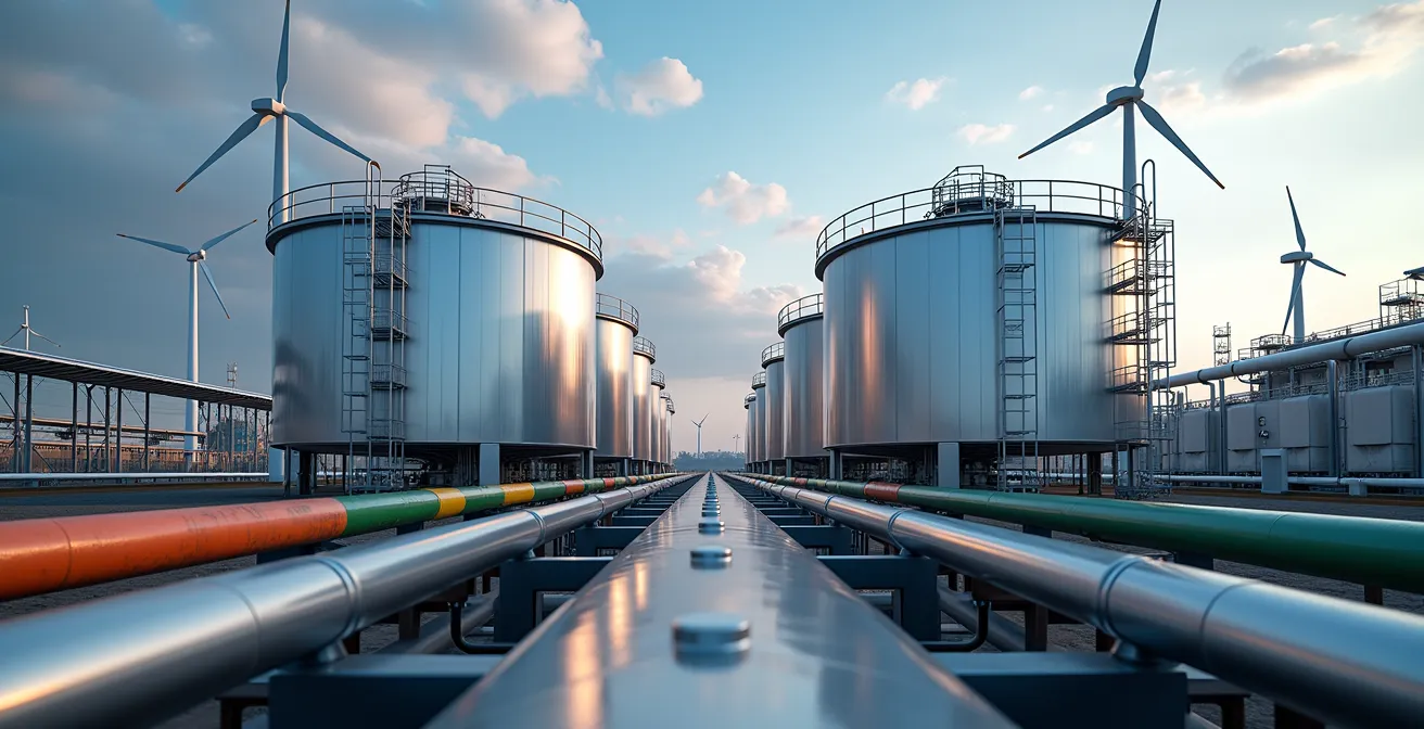
Solar or Wind? Choosing the Right Renewable System for UK Manufacturing Sites
As you work to increase your site’s energy resilience and control costs, generating your own renewable energy is the logical end-game. For UK manufacturing sites, the primary choices are solar photovoltaics (PV) and small-to-medium scale wind turbines. The right choice is not based on which technology is “better,” but on which generation profile best matches your site’s specific operational patterns, physical footprint, and local planning constraints. A single-shift, 9-to-5 operation has a very different energy demand profile from a 24/7, three-shift facility.
Solar PV is often the path of least resistance. Rooftop solar utilises existing, unused space and generally faces fewer planning permission hurdles than wind. Its generation profile peaks during daytime hours, making it a perfect match for a standard single-shift operation, directly offsetting your most expensive daytime electricity consumption. Furthermore, the market for solar is mature, with many providers offering “zero-CapEx” Power Purchase Agreements (PPAs). In a PPA, a third party installs and maintains the system on your roof at no cost to you, and you simply agree to buy the electricity it produces at a fixed, discounted rate for a set term.
Case Study: Integrated Renewables for Fleet Electrification
The feasibility of combining on-site generation with fleet charging is well-established. For instance, the company McKinstry, as part of its commitment to full fleet electrification, has successfully integrated on-site renewable energy, including rooftop solar and battery storage solutions, into its charging infrastructure. This demonstrates a viable, closed-loop model where a company generates its own clean energy to power its clean transport, maximising both environmental benefits and energy independence.
Wind turbines, on the other hand, offer the potential for 24/7 generation, making them a better fit for energy-intensive, multi-shift operations. A single, well-sited turbine can generate significantly more energy than a rooftop solar array. However, they come with major challenges in the UK context. They require a significant dedicated land area and face a much more difficult and lengthy planning permission process due to visual and environmental impact concerns. Maintenance is also more intensive and specialised than for a static solar array.
The optimal solution is often a hybrid approach, combining solar, wind, and the BESS we discussed earlier. This allows you to capture the advantages of each technology, creating a resilient and cost-effective energy ecosystem tailored to your site.
This comparative table summarises the key strategic considerations for a UK manufacturing site.
| Factor | Solar | Wind |
|---|---|---|
| Generation Profile | Daytime peak, ideal for single-shift | 24/7 potential, suits 3-shift operations |
| UK Planning Permission | Relatively easy for rooftop | Difficult, visual impact concerns |
| Space Requirements | Utilizes existing roof space | Requires dedicated land area |
| Maintenance | Minimal, panel cleaning | Regular turbine servicing required |
| Zero-CapEx Options | Roof lease PPA models available | Limited third-party options |
Your journey to fleet electrification is an opportunity to fundamentally re-evaluate and strengthen every aspect of your site’s infrastructure. By adopting a holistic, Megawatt-scale perspective, you can move beyond simply meeting a mandate and instead build a more resilient, efficient, and future-proofed manufacturing operation. Begin your comprehensive site infrastructure audit today to secure your production capacity for tomorrow.